3
Design and Function
24/130 ekr CON 100 – Installation and Operating Manual
3.7.2 Line and Contrast Sensor (Sensor3)
In conjunction with the CLSPro600 line and contrast sensor, the
controller permits guiding on continuous or interrupted printed
lines or contrast edges. In this case, the line and contrast sensor is
connected to the controller as Sensor 3.
The following applies for the installation position of the line and
contrast sensor:
The connecting cable of the line and contrast sensor points in the
direction of Sensor 2.
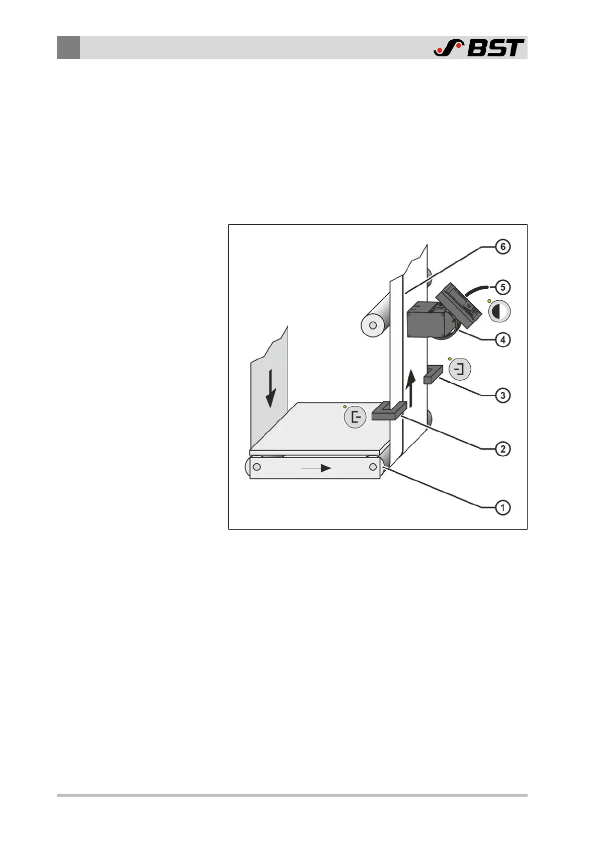
Fig.5: Installation position Sensor3
① Outfeed roll ④ Sensor 3
② Sensor 1 ⑤ Connecting cable Sensor 3
③ Sensor 2 ⑥ Printed line
In order to achieve optimum guiding results, the distance
between the sensors and the outfeed roll ① of the guiding
device must be kept as small as possible.
3.8 Accessories
For accessories and the order address, see Accessories and Spare
Parts, page 124.

 Loading...


