Operation
9
ekr CON 100 – Installation and Operating Manual 109/130
9.13 Displaying System Components
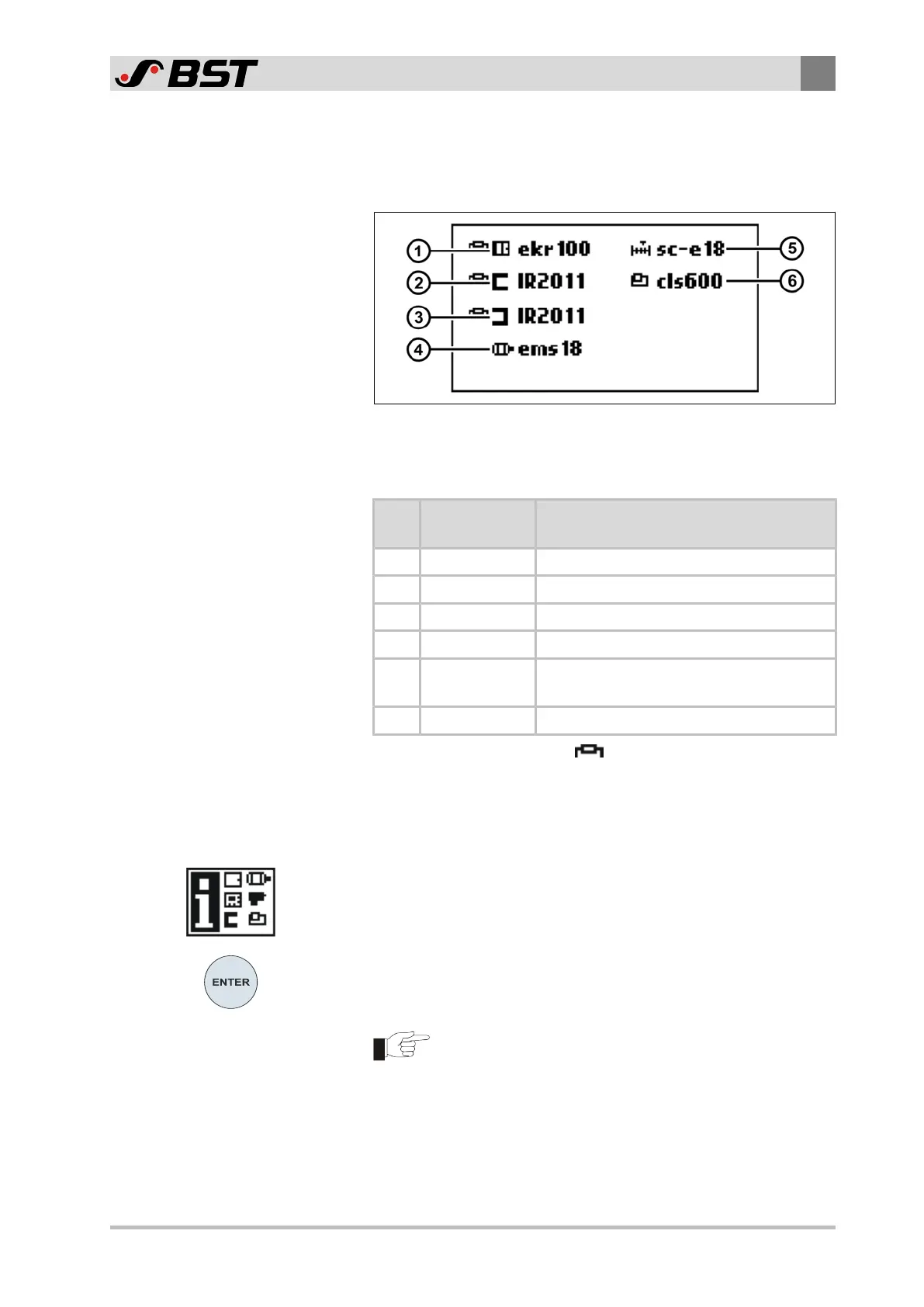
This service display indicates the system components that are
connected to the controller.
Fig.51: Display of the system components connected (example)
You will find the meaning for the individual symbols in the following
table.
Pos. System
components
Type (example)
① Controller ekrCON100
② Sensor 1 Optical sensor IR 2011
③ Sensor 2 Optical sensor IR 2011
④ Actuator Electric motor powered actuator EMS 18
⑤
Servo center
transducer
Position feedback of the actuator EMS18
(sc-e18)
⑥ Sensor 3 CLS Pro 600 line and contrast sensor
The symbol for a resistor (
) in front of the symbol of the
component indicates that the CAN bus (or a strand) is terminated
at this point using a terminating resistor.
Calling up the service display
1. Activate the service display System components in the setup
menu (see Calling up the Setup Menu, page 106).
The system components connected are shown on the display.
2. Press the ENTER key to quit the service display.
The operation screen is displayed.
After a pre-set time (Timeout) has elapsed, the service
display is automatically quit. The operation screen is
displayed.

 Loading...


