Electrical Connection
7
ekr CON 100 – Installation and Operating Manual 47/130
7.6 Sockets / Plugs
7.6.1 Overview
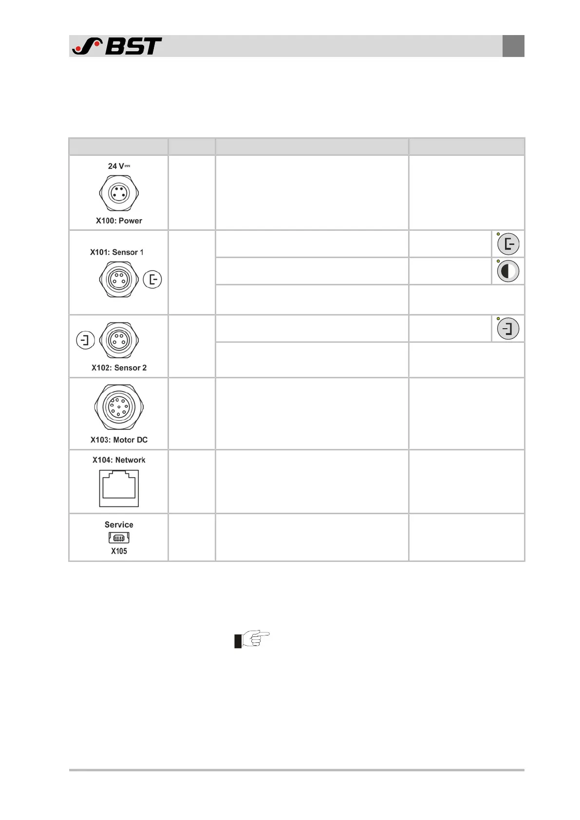
Socket / Plug Interface Function Note
Power Connection power supply 24V⎓
Wire cross section
0.5mm
2
CAN-Bus
Connection sensor 1 Guiding mode
Connection sensor 3 (CLSPro600)* Guiding mode
Connection DriveModule160*
(external output stage for actuator EMS23)
Alternative connection
on socket X102
CAN-Bus
Connection sensor 2 Guiding mode
Connection DriveModule160*
(external output stage for actuator EMS23)
Alternative connection
on socket X101
Analogue
Connection actuator
EMS18, EMS21, EMS22
Ethernet
Connection of an external control system
(e.g. PLC, PC, machine control system)
The network connection is
currently not supported!
USB Programming interface For service only!
* An optionally available CAN bus distributor is required for the
simultaneous connection of several bus participants to the
controller (see separate operating instructions of the components
to be connected).
The connector sockets of the controller are not Hot-Plug
capable.
►
Before adding or removing system components on the connector
sockets, electrically isolate the controller.

 Loading...


