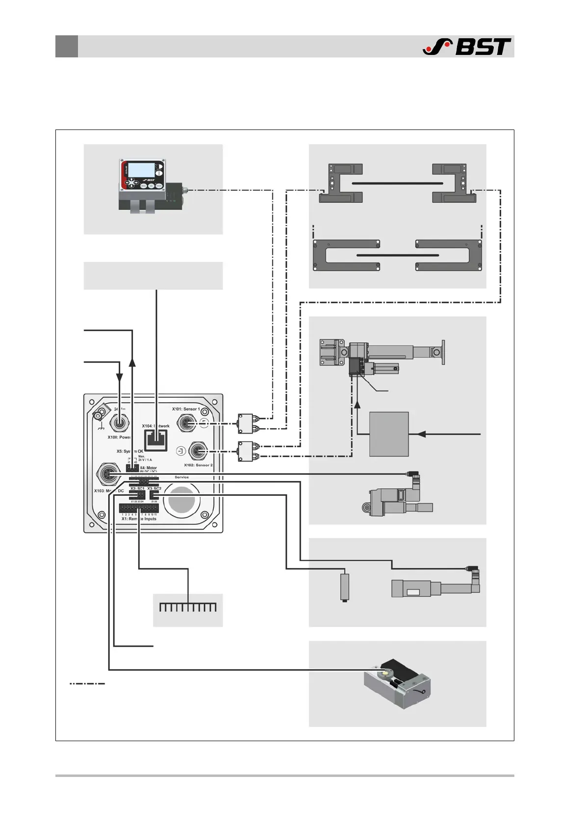
system that you can connect to the controller.
Line and contrast sensor Edge sensors
CLS Pro 600
IR 2011, IR 2012, US 2010
External control system
(e.g. PLC, PC, machine control system)
Actuator with position feedback
Actuator without position feedback
EMS23
Drive Module 160
CAN bus
distributor**
Remote control
Servo center
transducer
OMG 8,
CK 37
EMS 10,
ECO EMS 22
Motor brushless / DC
Controller
ekr CON 100
Bus line
** required for the connection of two
CAN-Bus participants to socket X101 / X102
EMS 18,
EMS 21,
EMS 22
Power
pack box
⎓
24 V
⎓
48 V
100 - 240 V
∿
(Use e.g. in EcoGuide)
Position feedback actuator
(alternative connection)
Message output
"System OK"
Wide array edge sensors*
* from firmware version 1.6.2
(see separate manual, document number MD. 532)
IR SEN ..., US SEN ...

 Loading...


