9
Operation
110/130 ekr CON 100 – Installation and Operating Manual
9.14 Displaying the DIL Switch Settings
This service display indicates the settings of the DIL switch on the
controller. This enables you to check the switch positions without
having to open the controller.
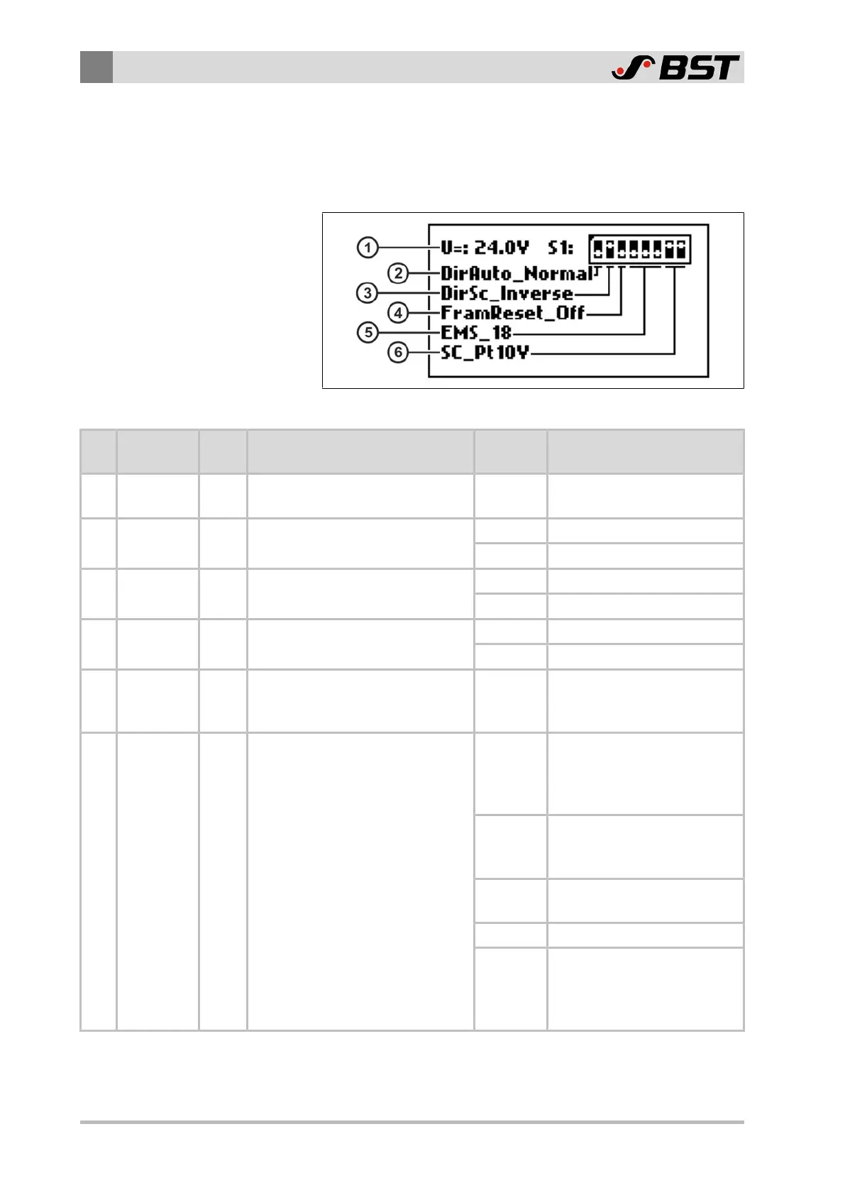
Fig.52: Display the DIL switch settings (example)
Pos. Designation DIL
switch
Function Status Meaning
① U=: Displays the operating voltage
24.0V
(Example)
The current operating voltage
is 24.0V⎓
② DirMotor S1.1
Reverse the motor rotation
direction
Normal Factory setting
Invrs. Direction of rotation inversed
③ DirSc S1.2
Reverse the guiding direction for
operating mode Center positioning
Normal Factory setting
Inverse Guiding direction inversed
④ FramReset S1.3
Activate memory reset
(for restoring the factory settings)
On Memory reset activated
OFF Memory reset deactivated
⑤ EMS
S1.4
S1.5
S1.6
Select the actuator used
18
(Example)
Type designation of the
actuator used
(example: 18 = EMS 18)
⑥ SC
S1.7
S1.8
Select the servo center transducer
used
Pt18V
Potentiometer
Signal input 0…18V⎓
(e.g. position feedback
EMS21, EMS22)
Pt10V
Potentiometer
Signal input 0…10V⎓
(e.g. position feedback EMS18)
Namur
Namur servo center trans-
ducer (e.g. OMG8, CK37)
EcoGuide EcoGuide
OFF
No servo center transducer
connected (operating mode
Center positioning cannot be
selected)

 Loading...


