Operation
9
ekr CON 100 – Installation and Operating Manual 77/130
9.3.2 Operation Display Edge Sensors (Sensor 1/2)
The operation displays for sensor 1 and sensor 2 appear only if the
respective edge sensors are connected to the controller.
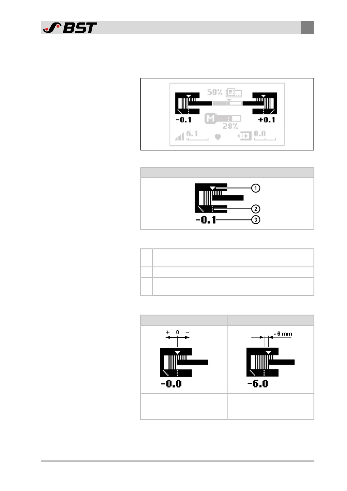
Fig.33: Operation displays edge sensors
Operating display edge sensor
Symbol meanings
①
The white triangle marks the set position of the web edge in
the sensor scanning area.
② The dashed line marks the center of the sensor scanning area.
③
The numeric value indicates the current web edge position
in the sensor scanning area (unit mm).
Displaying the web position (example)
Guiding setpoint = 0 Guiding setpoint = -6mm
The web edge is located in the
center of the sensor scanning
area.
The web edge is displaced by
-6 mm from the center of the
sensor scanning area.

 Loading...


