9
Operation
102/130 ekr CON 100 – Installation and Operating Manual
9.9 Setting the Guiding Setpoint
The guiding setpoint is the desired position of the web edge,
printed line or contrast transition in the sensor scanning area. It
can be adjusted in the Automatic operating mode using the arrow
keys.
The guiding setpoint is saved separately for each guiding
mode.
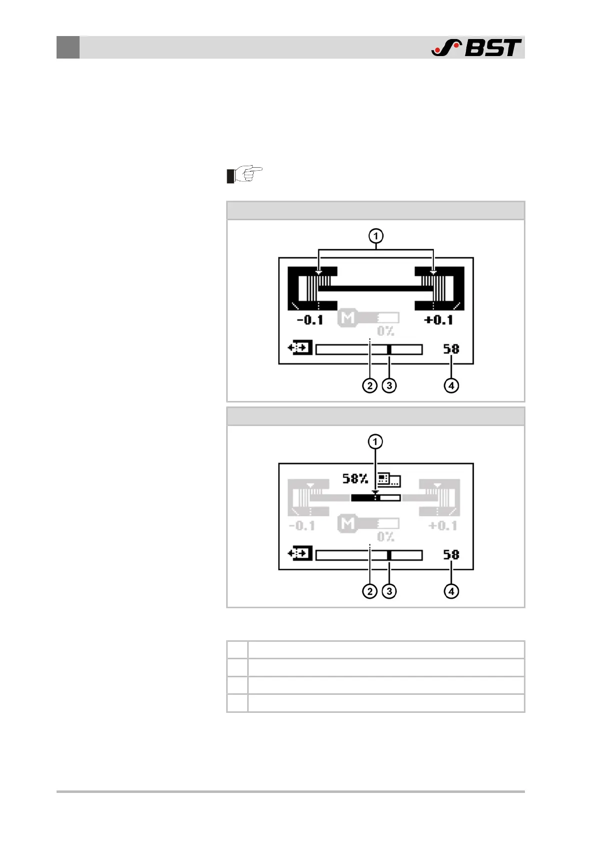
Display for edge sensors (Sensor 1, Sensor 2)
Display for line and contrast sensor CLSPro600 (Sensor 3)
Symbol meanings
① The triangle marks the guiding setpoint during operation.
② The dashed line marks the centre of the sensor scanning area.
③ The black bar marks the guiding setpoint
④ Numeric display of the guiding setpoint

 Loading...


