MVX250i E, MVX200i E, MVX200 E
DISASSEMBLING
1
1. Disassembling and Reassembling - (1)
Notes
(1) When replacing the flat cable with a new one, allow it to remain folded the same as the original part.
(2) The flat cable has a contact orientation to be engaged with the connector. Refer to the instructions in the disassembly procedure
diagram and interconnection diagram for boards.
(3) To secure screws, apply the Three Bond 1401B (CY9-8011-000)
(4) If any part to be replaced has UL tape attached on it, be sure to reattach UL tape at the same position in reassembling.
(5) Use the new type connector (MAIN P.C.B. CN102) as illustrated.
FPC
FPC
Lock
Unlock
Metal
contact
Metal
contact
(6) For replacing the fuse mounted on the MAIN P.C.B., it is required to remove the CVF unit.
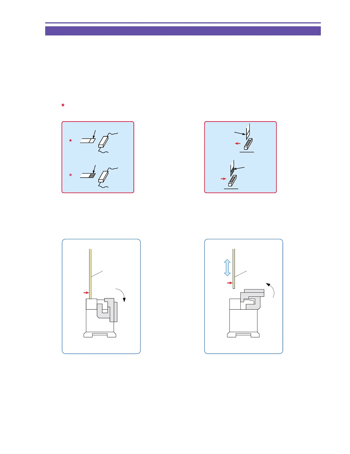
• Lateral engaging connector
( The instructions are given in the disassembly proce-
dure diagram and board interconnection diagram.)
: Contacts are positioned downward. (board side)
∗ : Contacts are positioned upward.
Metal contact (Pins' face up)
Metal contact (Pins' face down)
:
:
• Lengthwise engaging connector
( The instructions are given in the disassembly proce-
dure diagram and board interconnection diagram.)
Indicated by → Arrowheads indicate the contacts, and the
shafts indicate the noncontacts.
Metal contact
Metal contact