MVX250i E, MVX200i E, MVX200 E
SERVICE MODE · ADJUSTMENT
2
2. Setting
(1) Adjustments other than DMC-III : Perform adjustments in the product state.
(2) Tracking adjustment (DMC-III) and Envelope check : Perform them with the Setting A.
(3) Adjustments related to DMC-III other than Tracking adjustment, tape path system check and tape path system cleaning : Perform
them with the Setting B.
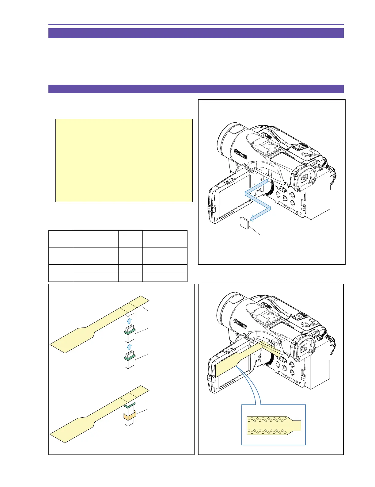
2-1 Using the Extension Connectors
(1) Attach the two extension connectors (DY9-1395-000) to the
extension flexible cable (DY9-1390-000)
Important
Secure the two connectors with tape as shown in
the figure. (When removing the extension con-
nector assembly from the main unit after use, the
connector coupling may be detached in some
cases. If the connector located on the main unit
side comes off, it becomes impossible to remove
it from the main unit. To prevent this, secure the
connectors with tape beforehand.)
(2) Detach the blindfold sheet.
(3) Connect the extension connectors to the CN2900.
<Signals used>
Fig. 3
Pin No.
Signal
Designation
2 EVF HD
3GND
15 SWP
19 PBRF
Pin No.
Signal
Designation
21 EVF R
22 EVF COM
23 EVF G
24 EVF B
Fig. 2
DY9-1390-000
DY9-1395-000
Secure with tape.
DY9-1395-000
Fig. 1
BLINDFOLD SHEET