MVX250i E, MVX200i E, MVX200 E
SERVICE MODE · ADJUSTMENT
3
2-2 Setting A
Envelope observation)
(1) Observe a PB-RF signal output from each extension connector that has been attached in 2-1 “Using the Extension Connectors”.
Tracking Adjustment)
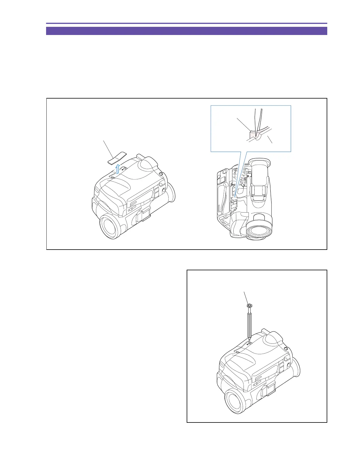
(1) Detach the regulation cover.
* : To avoid flawing the regulation cover, detach it from the inside of the left cover as illustrated.
(2) While observing a PB-RF signal, adjust the post to eliminate
fluctuations of the envelope.
Note : When the tracking adjustment is going to be per-
formed, refer to “5-9 Tape Path Adjustment” on
p.36.
Fig. 4
REGULATION COVER
LEFT COVER
REGULATION
COVER
Fig. 5
ADJUSTMENT DRIVER
(DY9-2053-000)