MVX250i E, MVX200i E, MVX200 E
TECHNICAL DESCRIPTION
14
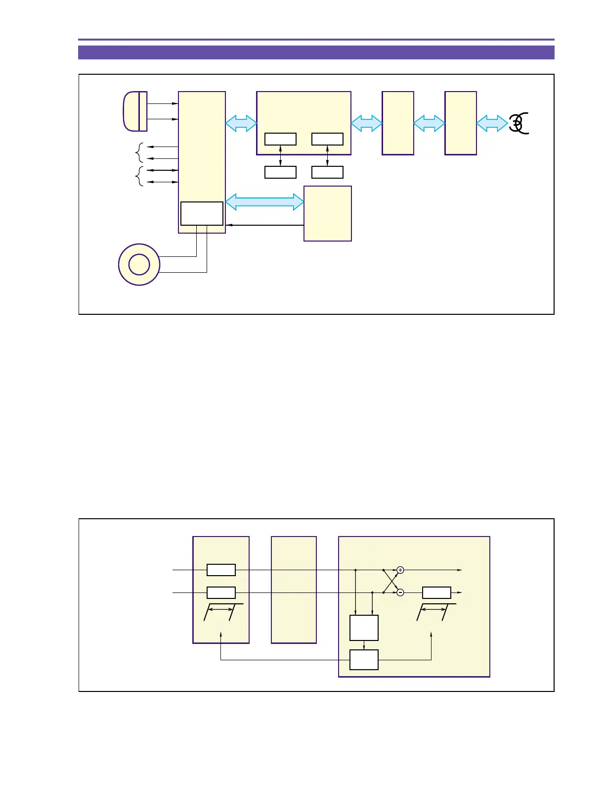
4-4 Audio Signal Flow
< AIF >IC801
Out ALC (Auto Level Control), fading, and amplification of various output signals. For the beep tone issued at ejection, etc., the
signal from the FR MI-COM is generated in the circuit and changed over in the AIF.
The microphone amplifier, HPF, ALC, A/D, D/A, and digital I/F, SPEAKER DRIVER with ALC circuits are contained in this IC.
It is also used for changeover between ordinary voice sound and beep sound.
< VIC4 >
The following processing operations are carried out for reducing noise from the DMC mechanism.
• Noise cancellation based on correlation of V-cycle noise components.
• Noise component reduction by means of trapping.
< Automatic wind noise cutting>
For efficient reduction of wind noise, the cutoff frequency of the wind noise cutting HPF circuit is regulated according to the
current level of wind noise.
Fig. 11
SPEAKER
DRIVER
FR
MI-COM.
IC801
AIF4
IC1103
DIGIC DV
IC2301
VIC4
IC2000
VRP2
+
−
L
L
R
L
R
R
MIC
HEAD
PHONE
AV
JACK
B EEP
Serial
SPEAKER
MEM IF CARD IF
SDRAM CARD
REC/
PB
HEAD
Fig. 12
AIF4 VIC4DIGIC
DV
(L)
(R)
L + R
L − R
MIC
IN
HPF
HPF HPF
WIND
DETECT
(L − R)
FR
MI-COM.
150Hz 600Hz 40Hz 3kHz