MVX250i E, MVX200i E, MVX200 E
DISASSEMBLING
13
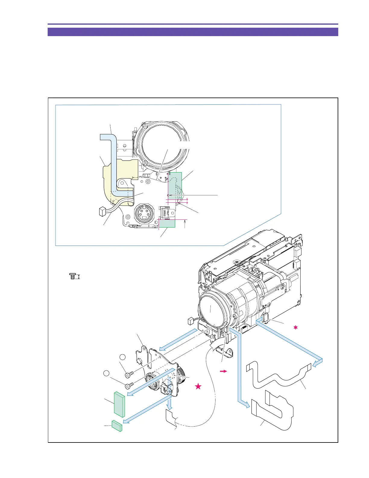
1-10 Separation of JACK 2 P.C.B.
(1) Detach the Cushion RC1 and RC2.
(2) Remove two screws (k × 2), disconnect the CN91, and detach the JACK2 P.C.B.
(3) Detach the CAV-JACK1 FPC and MAIN-JACK1 FPC from the CN701 and CN2101.
<Note on Reassembling>
(1) Before mounting the JACK2 P.C.B., run the MAIN-JACK1 FPC, CAV-JACK1 FPC, and MAIN-JACK1 Cable through groove A.
(2) Attach the Cushion RC1 and RC2 to the position indicated in the figure below.
Fig. 10
k
2.5mm
Metal
M1.7
Note on Reassembling (1),(2)
JACK2 P.C.B.
CAV-JACK1 FPC
CAV-JACK1 FPC
MAIN-JACK1 FPC
MAIN-JACK1 FPC
MAIN-JACK1 Cable
(2)
(3)
(3)
CN91
(2)
CN701
CN2101
Groove A
(1)
(1)
Align to the
hole center.
Align to a point 1.5 mm above
the edge of the P.C.B.
Align to the outline
of the DV Connector.
(2) - k
(2) - k
Cushion RC1
Cushion RC2
Cushion RC1
Cushion RC2
1.5mm
JACK2 P.C.B.