MVX250i E, MVX200i E, MVX200 E
SERVICE MODE · ADJUSTMENT
16
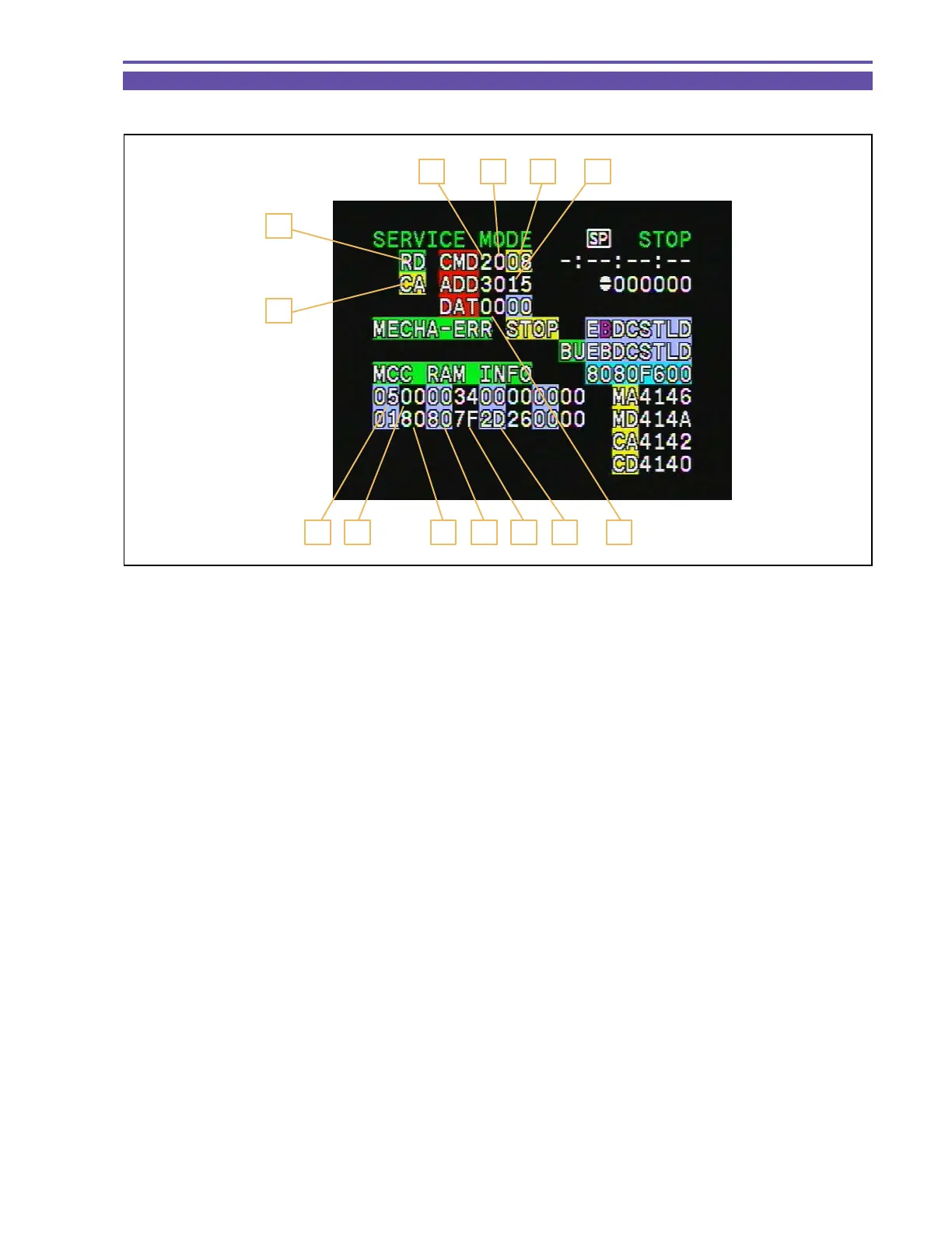
Fig. 15
3
1
2
4 5
8 9 10 11 12 13 6
7
5-1-1 Indication in Service Mode
Shown below are the indications in the service mode.
1. MODE : Indicates the MODE currently selected. (RD/WR/ST)
2. Indicates for which block the command is specified. (MA, MD, CA, CD, etc.)
3. CS : Indicates the Chip Select currently specified. (0~F)
4. Function : Indicates the Function currently selected. (00~FF)
5. ADDR : Indicates the ADDRESS currently selected. (0000~FFFF)
6. DT : Indicate, in hexadecimal representation, the DATA currently being read or set. (00~FF)
7. Data write status (0 : Read mode, 1 : Ready to write, C : Write execution)
8. ST : Adjustment status (02: During adjustment, 05: Adjustment OK, 09: Adjustment NG)
9. ST2 : Adjustment status (for use in AF adjustment)
At the time of IS adjustment
10. IS1 : Yaw Gyro gain
11. IS2 : Pitch Gyro gain
12. IS3 : Yaw Gyro offset
13. IS4 : Pitch Gyro offset