MVX250i E, MVX200i E, MVX200 E
TECHNICAL DESCRIPTION
13
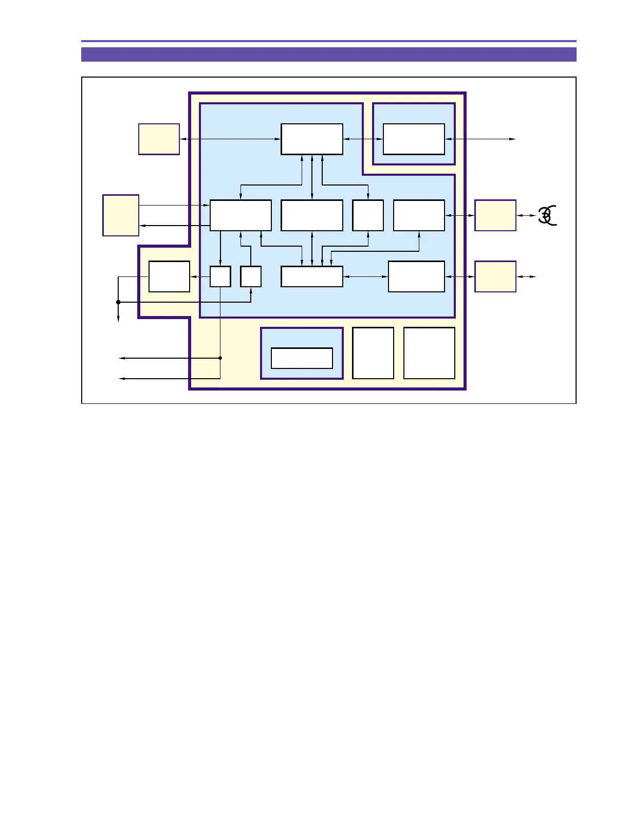
4-3 Recorder Signal Processing
< VIC4 >IC2301
• The VIC, MI-COM, DIF INTERFACE and VIDEO INTERFACE circuits are integrated on a single semiconductor chip.
• A/B DATA : Input in camera mode. B DATA is output and A DATA is input at playback. (DIGIC DV digital effect circuit is
used at playback.)
The video data and signals input to VIC4 are subjected to digital VCR format signal processing. Audio data,
subcode data and ITI data are also created at VIC4, and these signals are output to VRP2 as 41.85 Mbps data of
DV format.
• DIF : After conversion to digital data conforming to IEEE1394 standard, the data is output at DV terminal. At digital
input, the data enters VIC4 signal processing circuit via the opposite route.
< VRP2 >IC2000
Recording data of 41.85 Mbps output from VIC4 is amplified at VRP2, and is recorded on magnetic tape while undergoing head
switching of CH-1, CH-2 with a switching pulse. At playback, the head output signal is amplified and sent to VIC4.
Fig. 10
AV JACK
S TERMINAL
CVF
LCD
LCD
IC1103
DIGIC
DV
VIDEO
INTERFACE
A DATA
B DATA
R,G,B
D/A
75Ω
DRIVE
A/D
IC2302
SDRAM
REC/PB
PROCESS
ECC
COMPRESSION
/DEMOD.
BUS
IC2301
VIC4
VIC BLOCK DIF BLOCK
MI-COM. BLOCK
SDRAM
INTERFACE
DIF
INTERFACE
FR MI-COM.
Cache
1K Byte
CO-
processer
AUDIO
INTERFACE
IC2000
VRP2
DV
TERMINAL
AV
JACK
IC801
AIF4
VIDEO
HEAD