MVX250i E, MVX200i E, MVX200 E
DISASSEMBLING
45
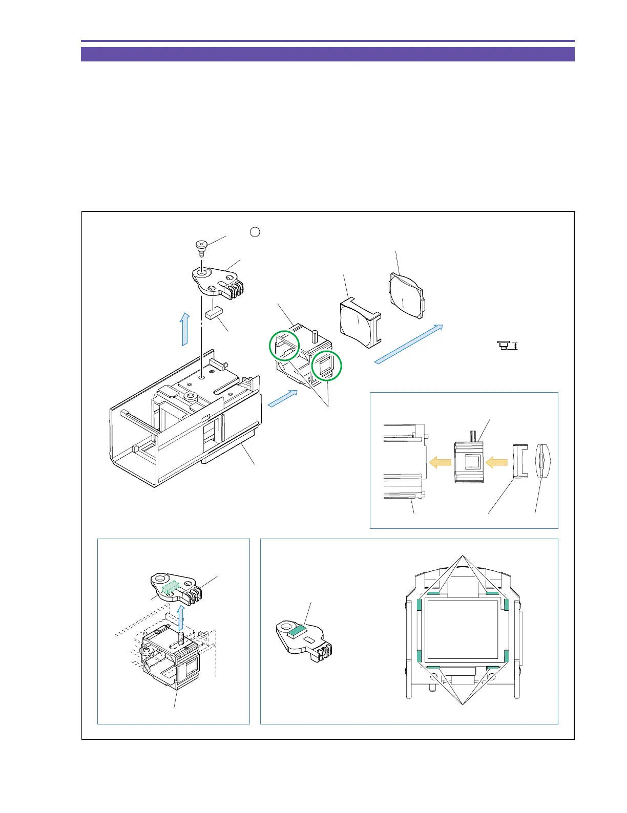
1-34 Disassembly of CVF Unit - 5
(1) Remove one screw (r × 1), and detach the CVF Knob, Rubber, and CVF Lens Holder.
(2) Disengage two claws A, and detach the Lens1 and Lens2.
<Note on Reassembling>
(1) When attaching the Lens1 and Lens2 to the CVF Lens Holder, take care not to mistake the orientation of the Lens1/Lens2.
(2) When attaching the CVF Knob, engage the dowel of the CVF Lens Holder as illustrated below. Take care not to forget to attach the
Rubber.
<Instruction for Supply>
CVF Inner Cover inside, 8 points on sliding rail part : Hanal KS-39M (DY9-3053-000)
Rubber top surface : Hanal KS-39M (DY9-3053-000)
r
2.3mm
Metal
M1.7
Steped Screw
Instruction for Supply
Note on Reassembling (2)
Note on Reassembling (1)
CVF Inner Cover
(1)
CVF Knob
(1)
(2)
Claw A
Rubber
CVF Lens Holder
Lens 1
Lens 2
CVF Lens Holder
CVF Inner Cover Lens 2
Lens 1
Rubber top surface
Hanal : KS-39M
Sliding parts of rail
CVF Knob
CVF Lens Holder
(1) - r
Rubber
Sliding parts of rail
Fig. 42