SECTION 4 - ELECTRICAL SYSTEM SERVICE
page 4-6
Remote Switch Installation
107018C
203194M2
203195M2
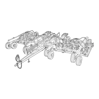
REMOTE SWITCH ASSEMBLY
REF DESCRIPTION
1 REMOTE SWITCH ASSEMBLY
2 U-BOLT 5/16" x 4 1/8" W x 4 3/4" D
3 U-BOLT BRACKET FOR 2,3 & 4
4
LOCKNUT 5/16" UNC
5 SPRING-E .08WR .75D 9L
6 CHAIN #8, 24"LONG
7 KEY RING
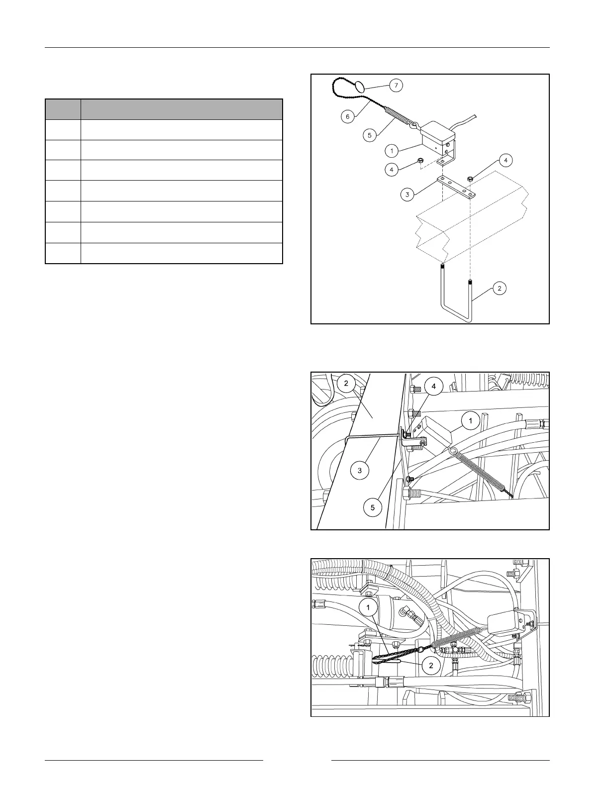
Fasten the remote switch assembly (1) to the to the center
of the front cross tube (2) with a 5/16" u-bolt (3), u-bolt
bracket (5) and 5/16" locknuts (4) as shown. The switch
assembly (1) will mount to the u-bolt bracket (5) using one
of the u-bolt locknuts (4).
Loop the chain (1) through one of the subbar gang tube V-
bolts (2) and secure the chain with the key ring. Refer to
the ‘Adjustments’ section to determine the length of chain
required for proper operation.
Refer to the ‘Switch Wire Routing’ section for electrical
wire routing.