161
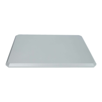
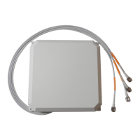
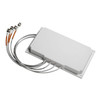
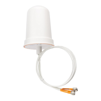
Cisco Aironet Four-Port Dual-Band Polarization-Diverse Antenna (AIR-ANT2513P4M-N)
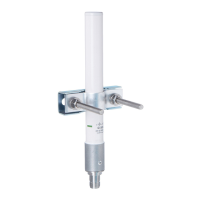
Figure 6 Assembling the Bracket Hardware
5. Make sure you orient the antenna correctly (note the arrow on the back of the antenna that indicates the top of the antenna).
Use a 1/2 in. (13-mm) wrench to loosen the elevation adjustment bolt and the elevation pivot bolt.
6. Adjust the azimuth (side-to-side position) and elevation (up-and-down position) of the antenna. Loosen the adjustment
bolts slightly to allow for adjustment. Azimuth angle can be adjusted ±25 degrees and elevation can be adjusted ±60
degrees. You can use the azimuth and elevation markings on the mounting arm and the wall flange as a guide.
7. After you adjust the antenna position, tighten the adjustment bolts and the pivot bolts. Tighten all bolts to 18.7 +/- 5 lb-ft
(25.4 Nm).
8. Connect the antenna cables to the access point. The antenna ports are labeled A through D, from left to right.
— On the AP3702P, connect the antenna port A to connector A on the access point, antenna port B to connector B, and
so on.
— On the AP1570, connect antenna port A to Port 1 on the AP, antenna port B to port 2 on the AP, and so on.
See the Suggested Cable section for cable recommendations.
 Loading...