5
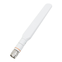
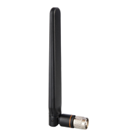
Cisco Aironet Dual-Band Omni-Directional Antenna (AIR-ANT2568VG-N)
Communications, Services, and Additional Information
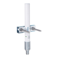
Choosing a Mounting Location
The antenna is designed to create an omni-directional broadcast pattern. To achieve this pattern, the access point should
be mounted clear of any obstructions to the sides of the radiating element. If the mounting location is on the side of a
building or tower, the antenna pattern is degraded on the building or tower side.
Generally, the higher an antenna is above the ground, the better it performs. A practice is to install your antenna about 5
to 10 ft (1.5 to 3 m) above the roof line and away from all power lines and obstructions.
Tools and Equipment Required
No tools are required to mount the antenna to the access point. However, you may need a ¾ in. (19 mm) open end or
combination wrench (or adjustable wrench) to remove the antenna port covers.
For information about tools required to mount the access point, see the appropriate access point documentation.
Mounting the Antenna
To connect the antenna to the access point:
1. If necessary, remove the antenna port cover.
2. Align the antenna N connector with the appropriate antenna port.
3. Gently push the antenna into the port.
4. Tighten the antenna hand tight.
Communications, Services, and Additional Information
To receive timely, relevant information from Cisco, sign up at Cisco Profile Manager.
To get the business impact you’re looking for with the technologies that matter, visit Cisco Services.
To submit a service request, visit Cisco Support.
To discover and browse secure, validated enterprise-class apps, products, solutions and services, visit Cisco
Marketplace.
To obtain general networking, training, and certification titles, visit Cisco Press.
To find warranty information for a specific product or product family, access Cisco Warranty Finder.
The following information is for FCC compliance of Class A devices: This equipment has been tested and found to comply
with the limits for a Class A digital device, pursuant to part 15 of the FCC rules. These limits are designed to provide
reasonable protection against harmful interference when the equipment is operated in a commercial environment. This
equipment generates, uses, and can radiate radio-frequency energy and, if not installed and used in accordance with
the instruction manual, may cause harmful interference to radio communications. Operation of this equipment in a
residential area is likely to cause harmful interference, in which case users will be required to correct the interference at
their own expense.
The following information is for FCC compliance of Class B devices: This equipment has been tested and found to comply
with the limits for a Class B digital device, pursuant to part 15 of the FCC rules. These limits are designed to provide
reasonable protection against harmful interference in a residential installation. This equipment generates, uses and can
radiate radio frequency energy and, if not installed and used in accordance with the instructions, may cause harmful
interference to radio communications. However, there is no guarantee that interference will not occur in a particular
 Loading...