SAILOR 900 VSAT High Power system
2-6 Chapter 2: Introduction 98-150471-A02
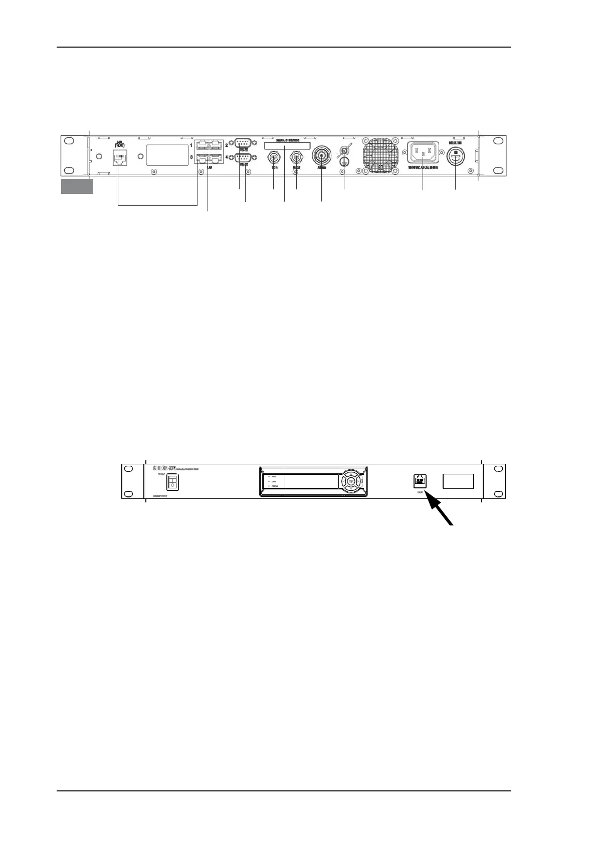
ACU interfaces
The ACU has the following interfaces and switch:
• N-connector for ADU cable (50 Ohm).
• 2 x F connectors for Rx and Tx cables (75 Ohm) to VSAT modem.
• Multi connector for NMEA interfaces (for input from GPS compass or Gyro compass).
• RS-422 interface for modem control.
• RS-232 interface for modem control.
• 4 x LAN ports for VSAT modem control and user equipment (i.e. for SAILOR
FleetBroadband service communication line or WAN port for VSAT Internet).
•AC input.
•On/Off power switch
The ACU has additionally a LAN connector at the front for accessing the service port from
the ACU front panel.
Installation friendly
The ACU comes in a 19” rack version.
Service friendly
You can do remote diagnostics and service with the ACU. Its built-in test equipment checks
constantly the device for proper functioning. It performs POST (Power On Self Test) and
you can request a PAST (Person Activated Self Test). Continuous Monitoring (CM) is also
available. BITE error codes can be read out in the web interface and in the display of the
ACU.
Software update is done via a connected PC and the built-in web interface of the ACU.
Figure 2-5: SAILOR 900 VSAT High Power ACU, connector overview
/$16HUYLFHWRIURQW
7[,Q
5[2XW
*URXQG
/$1
/$10RGHPFRQWURO
56 10($
$&3RZHU
56
$QWHQQD
$&8
)XVH$76%
7\SHODEHO
Figure 2-6: SAILOR 900 VSAT High Power ACU
SAILOR900HP.book Page 6 Monday, July 18, 2016 12:44 PM