To install the dual-antenna mode (optional)
98-150471-A02 Chapter 3: Installation 3-27
3. Provide vessel heading input to the master ACU and slave ACU, see NMEA 0183
connector on page 4-3.
4. Connect the cables as shown below and in the table below.
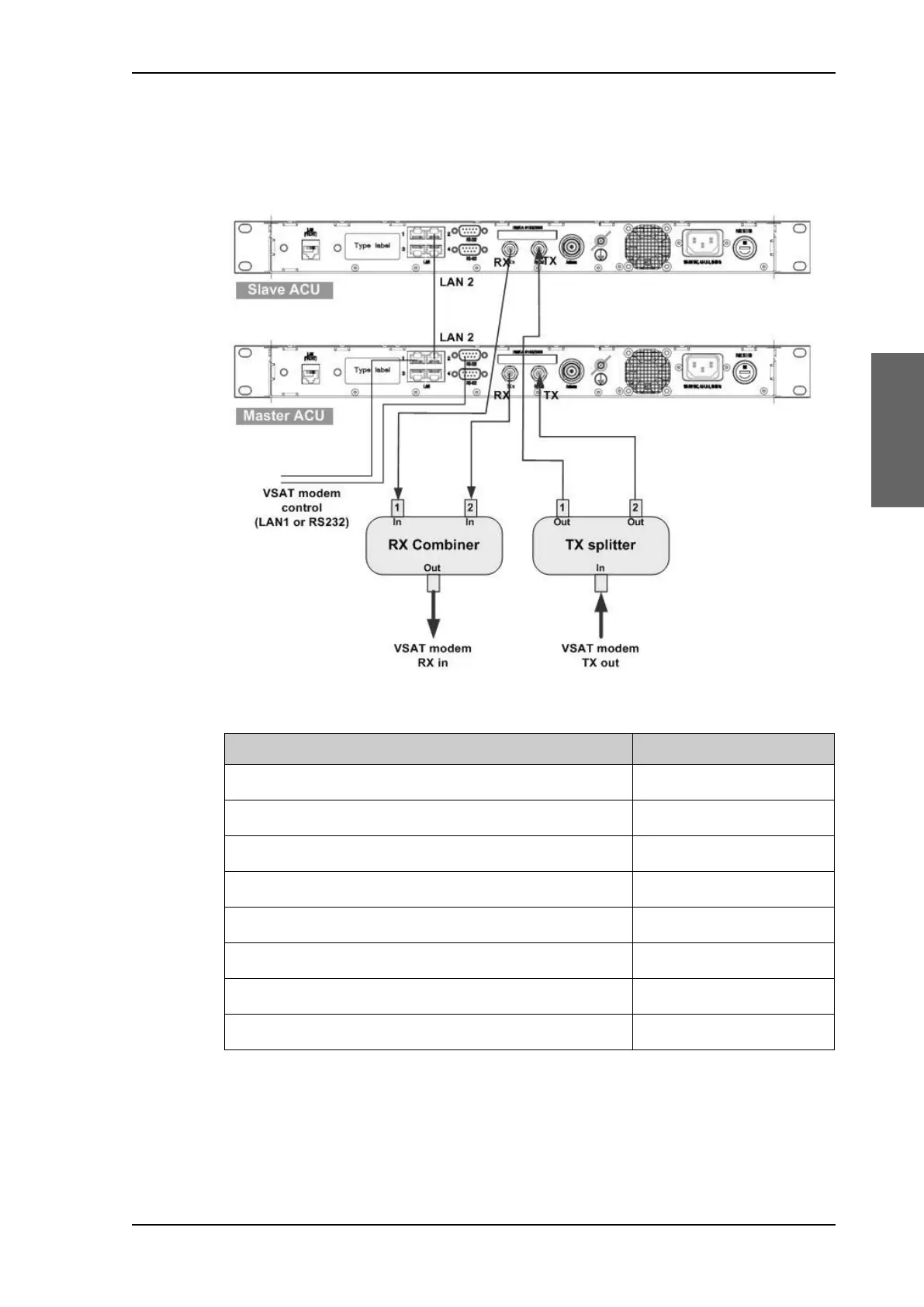
Figure 3-26: Dual mode antenna, connecting cables (example)
Connect cables Purpose
Master ACU LAN to Slave ACU LAN Master/Slave control
Master ACU LAN port 1 or RS 232 to VSAT modem control VSAT
modem control
Master ACU Rx Out to the Rx combiner input 1 Rx when Master active
Slave ACU Rx Out to the Rx combiner input 2 Rx when Slave active
Rx combiner output to VSAT modem Rx Rx to VSAT modem
Master ACU Tx In to the Tx splitter output 1 Enabled when Master active
Slave ACU Tx In to the Tx splitter output 2 Enabled when Slave active
Tx splitter input to VSAT modem Tx Tx from VSAT modem
Table 3-8: Dual mode antenna, cabling
SAILOR900HP.book Page 27 Monday, July 18, 2016 12:44 PM