Installation of the ADU
3-20 Chapter 3: Installation 98-150471-A02
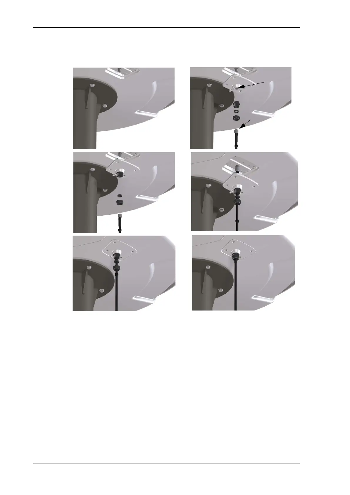
diameter. See also N-connector interface on the ADU on page A-7 for a more detailed
drawing how to connect the N-connector on the ADU.
Ensure that the connector assembly is properly protected against seawater and
corrosion. As a minimum, wrap it with self-amalgamating rubber.
9. Put the protection plate in place and fasten the 4 bolts (picture 5).
10.Fasten the nut.
Where the cables are exposed to mechanical wear — on deck, through bulkheads, etc. –
protect the cables with steel pipes. Otherwise, follow standard procedures for cabling in
ship installations.
Maximum allowed RF loss in the ADU cable
Maximum allowed cable loss is 20 dB at 1700 MHz. This is to ensure optimum
performance of the system.
Figure 3-18: SAILOR 900: Connecting the ADU cable
Protection plate
N connector
1
2
3
4
5
6
SAILOR900HP.book Page 20 Monday, July 18, 2016 12:44 PM