Interfaces of the VMU
98-150471-A02 Chapter 4: Interfaces 4-5
4.1.6 LAN1, LAN2, LAN3 and LAN4 connectors
Four Ethernet connectors (type RJ45) for PC/lap tops, routers, wireless access points. The
maximum cable length per connection is 100 m. Depending on the VMU connected, a LAN
connector may be used for modem control.
Cable type: CAT5, shielded.
For information how to configure the LAN network see To configure the LAN network on
page 6-30.
4.2 Interfaces of the VMU
For interfaces of the VMU and how to connect a VMU correctly to the ACU the user
documentation of the VMU. For step-by-step guidelines how to set up the VSAT modem
see Appendix C, VMU settings.
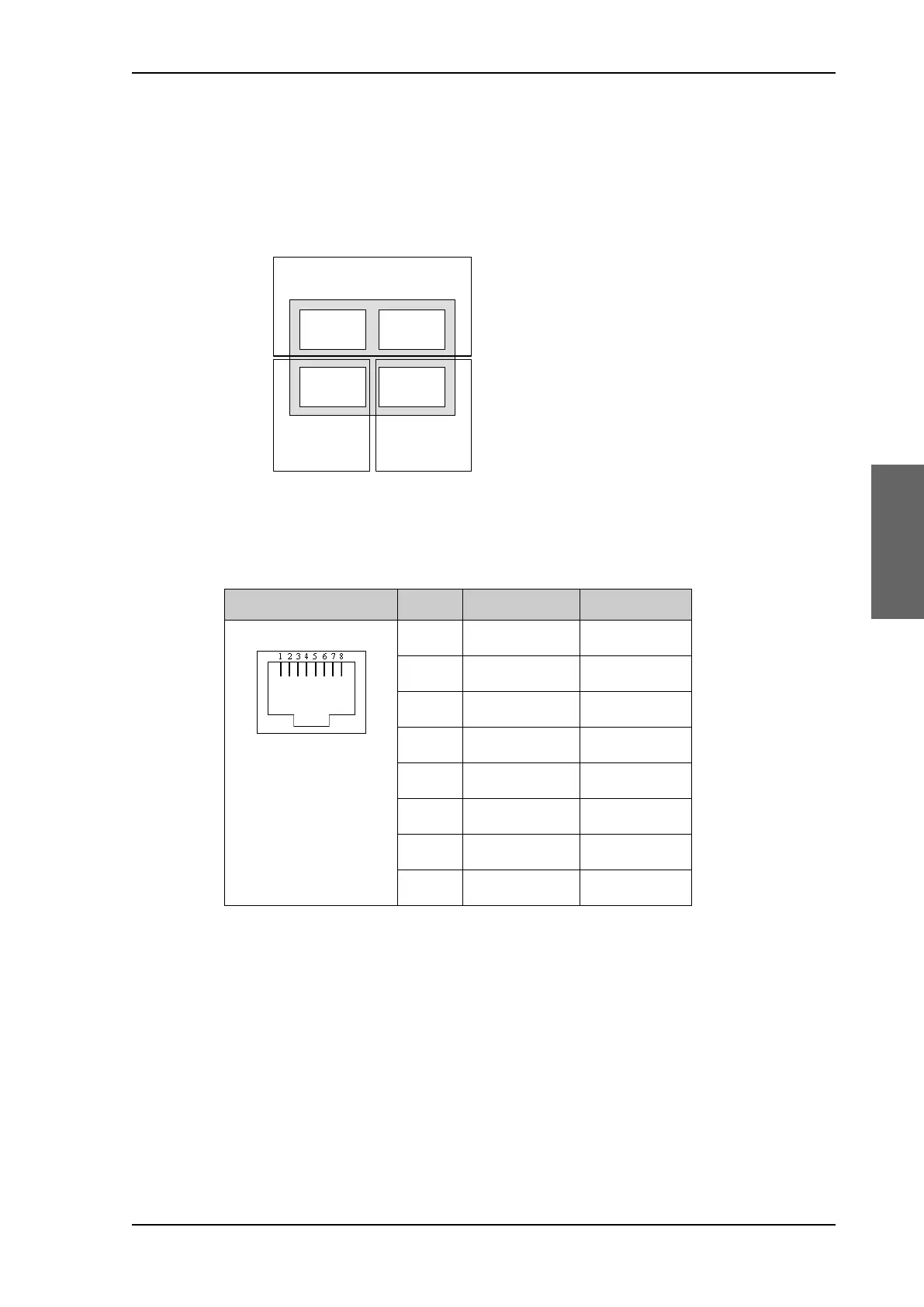
Figure 4-4: LAN connectors
Outline Pin Pin function Wire color
1Tx+ White/orange
2Tx- Orange
3 Rx+ White/green
4 Not connected Blue
5 Not connected White/blue
6Rx- Green
7 Not connected White/brown
8 Not connected Brown
Table 4-6: Ethernet connector, outline and pin assignment
3RUW 3RUW
3RUW 3RUW
6HUYLFHSRUW
1HWZRUN
96$7PRGHPFRQWURO
1HWZRUN
1HWZRUN
SAILOR900HP.book Page 5 Monday, July 18, 2016 12:44 PM