Calibration
98-150471-A02 Chapter 6: Configuration 6-17
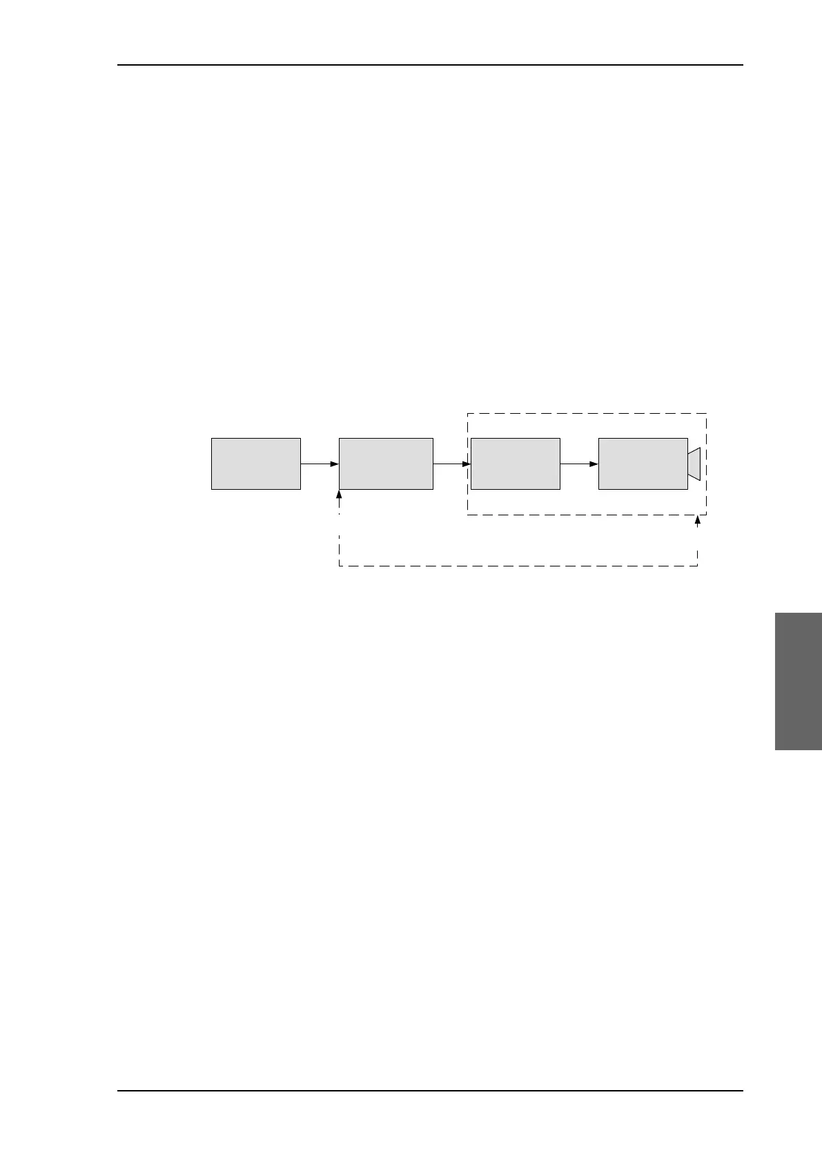
6.2.8 Fixed TX gain principle
The SAILOR 900 VSAT High Power uses a new transmitter chain concept. After calibration it
provides a fixed gain of 48 dB from the Tx-port of the ACU to the output of the BUC. The
advantages of the fixed TX gain principle are:
• Fixed TX gain over frequency and cable length
• TX gain independent of antenna cable length
• Utilization of the full 20 W BUC power over frequency
• P1dB compression point the same over frequency
When installing the SAILOR 900 VSAT High Power you make a cable calibration. At that
point every installation finds the same P1dB compression setting regardless of cable length.
The P1dB compression point is approximately -5 dBm at the ACU Tx-port. Additionally the
SAILOR 900 VSAT High Power system monitors the TX gain in real time.
* You find the maximum cable loss at Maximum allowed RF loss in the ADU cable on
page 3-20.
Example: ACU Tx-port power: -5 dBm > BUC output = +43 dBm (compression)
Figure 6-13: Fixed TX gain principle
:DWW%8&96$70RGHP
6$,/25+3
$&8
,QWHUIDFH
0RGXOH
6$,/25+3$'8
)L[HGJDLQaG%
LQGHSHQGHQWRIIUHTXHQF\%8&YDULDWLRQDQGFDEOHORVV
&DEOH
ORVV
$&8
7[SRUW
%8&RXWSXW
3G% G%P
SAILOR900HP.book Page 17 Monday, July 18, 2016 12:44 PM