Interfaces of the SAILOR 900 VSAT High Power ACU
4-4 Chapter 4: Interfaces 98-150471-A02
Recommended NMEA 0183 cable:
Two-wire constructed with one enclosed shield
Network signal pair:
• Size: No. 24 AWG (0.24 sq. mm) or heavier
• Characteristic impedance: 95 - 140 Ohm
• Propagation delay: 5 nanoseconds per meter, maximum
• 15 Twists (minimum) per meter
4.1.5 RS-232 and RS-422 connectors
Use these connectors to connect the ACU to the VSAT modems with serial interfaces. See
Interfaces of the VMU on page 4-5 for further details about the RS-232 or RS-422
connector.
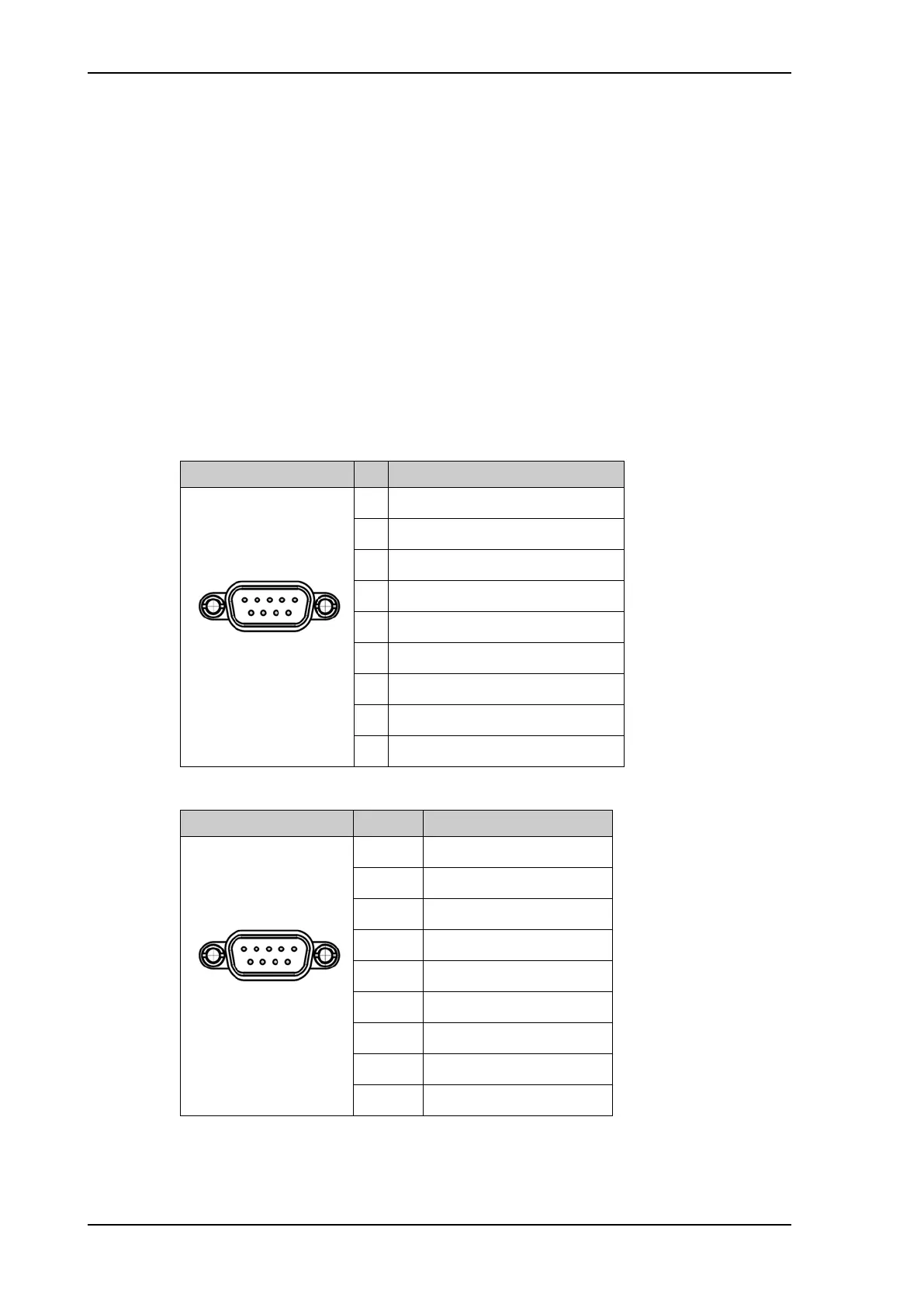
Outline (on the ACU) Pin Pin function
1 Not connected
2RXD
3TXD
4DTR
5Ground
6DSR
7RTS
8CTS
9 Receive Signal Strength Indicator
Table 4-4: RS-232 connector, male, outline and pin assignment
Outline (on the ACU) Pin Pin function
1Ground
2Line A RXD (+)
3Line B TXD (+)
4Ground
5Ground
6 Not connected
7Line A RXD (-)
8Line B TXD (-)
9 Not connected
Table 4-5: RS-422 connector, male, outline and pin assignment
SAILOR900HP.book Page 4 Monday, July 18, 2016 12:44 PM