Site preparation
98-150471-A02 Chapter 3: Installation 3-5
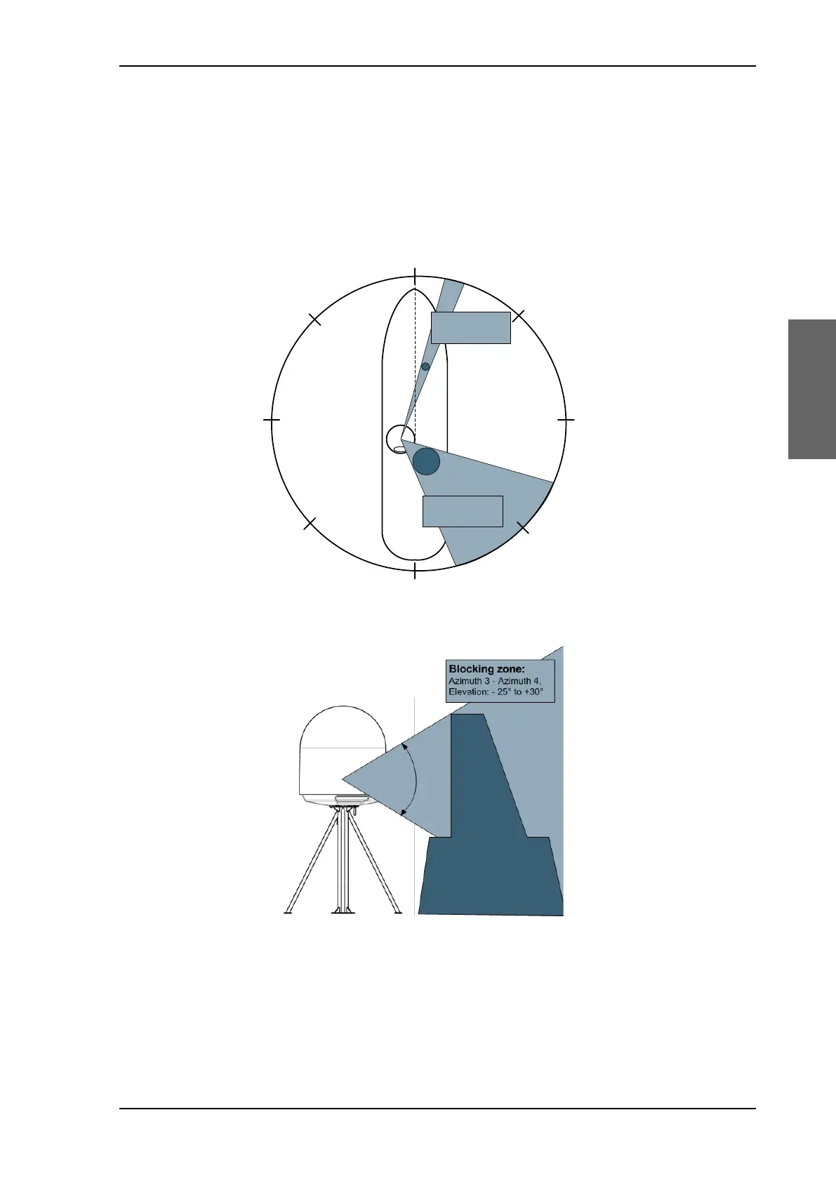
3.2.3 Blocking zones – azimuth and elevation
Your installation may require that you set up blocking zones for the ADU, i.e. areas where
the ADU will not transmit and areas where transmit power is potentially dangerous for
persons frequently being in these zones. You can set up 8 blocking zones. Each blocking
zone is set up with azimuth start and stop, and elevation angle.
The blocking zones are set up in the built-in web interface of the ACU. For further
information see To set up blocking zones (RX and TX) on page 6-28.
Figure 3-2: 2 blocking zones w, azimuth (example)
Figure 3-3: Blocking zone w, elevation angle (example)
$QWHQQD
2EVWUXF
WLRQ
$]LPXWK
$]LPXWK
$]LPXWK
$]LPXWK
%ORFNLQJ]RQH
$]LPXWK$]LPXWK
(OHYDWLRQWR
%ORFNLQJ]RQH
$]LPXWK$]LPXWK
(OHYDWLRQWR
SAILOR900HP.book Page 5 Monday, July 18, 2016 12:44 PM