Installation of the VMU
98-150471-A02 Chapter 3: Installation 3-25
3.4.2 To ground the ACU
Make sure that the grounding requirements are met. See the appendix Grounding and RF
protection on page F-1 for details about grounding.
ADU cable
The ADU is connected to the ACU with the ADU cable (coax cable) with an N connector at
both ends. For information on ADU grounding, see To ground the ADU on page 3-22.
At the ACU end, it is strongly recommended to ground the ADU cable. Use a short cable
from the ACU to a grounding point in the rack and connect the short cable to the ADU
cable at this grounding point, making sure the shield of the connector is properly connected
to the rack.
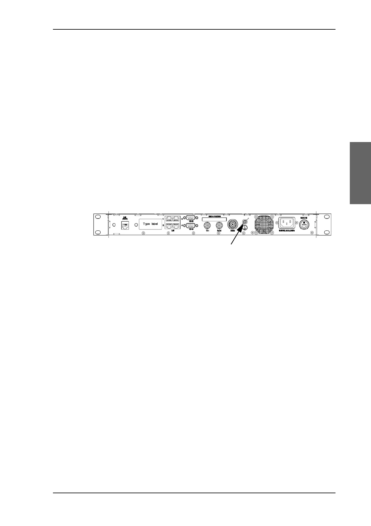
Ground stud at the ACU
To ensure that the ACU is grounded – also if the ADU cable is disconnected from the ACU,
connect an extra ground wire from the rack to the ground stud on the ACU. This ground
wire must be a heavy wire or braid cable with a larger diameter than the coax cable.
3.5 Installation of the VMU
For a list of supported VSAT modems see the SAILOR 900 VSAT High Power data sheet or
Figure 6-17: Web interface: SETTINGS, Modem profile – supported modems.
3.5.1 General mounting considerations — VMU
1. Mount the VMU close to the ACU, preferably at a distance < 1 m.
2. Connect all cables. See VMU settings on page C-1 for guidelines how to connect one of
the supported VSAT modems.
3. For cable specifications see VMU cables on page B-1.
Connectors and pin-out of the VMU
For connectors and pin-out see the user documentation of the VMU and Interfaces of the
VMU on page 4-5.
Wiring Power
Provide power to the VMU, see the user documentation of the unit.
Figure 3-24: ACU, ground stud
SAILOR900HP.book Page 25 Monday, July 18, 2016 12:44 PM