Cab Load Disconnect Switch
WARNING
Turning the cab load disconnect switch (CLDS) to
the off position does not disconnect power to all
electrical components (e.g. the starter and
sSAM). To work on the vehicle safely, the nega-
tive leads must be disconnected from the battery.
IMPORTANT: The ignition should be turned off
before turning the cab load disconnect switch on
or off.
The cab load disconnect switch (CLDS) is an op-
tional switch that can be used to open (turn OFF) or
close (turn ON) circuits between the battery and the
battery cable access box (BCA).
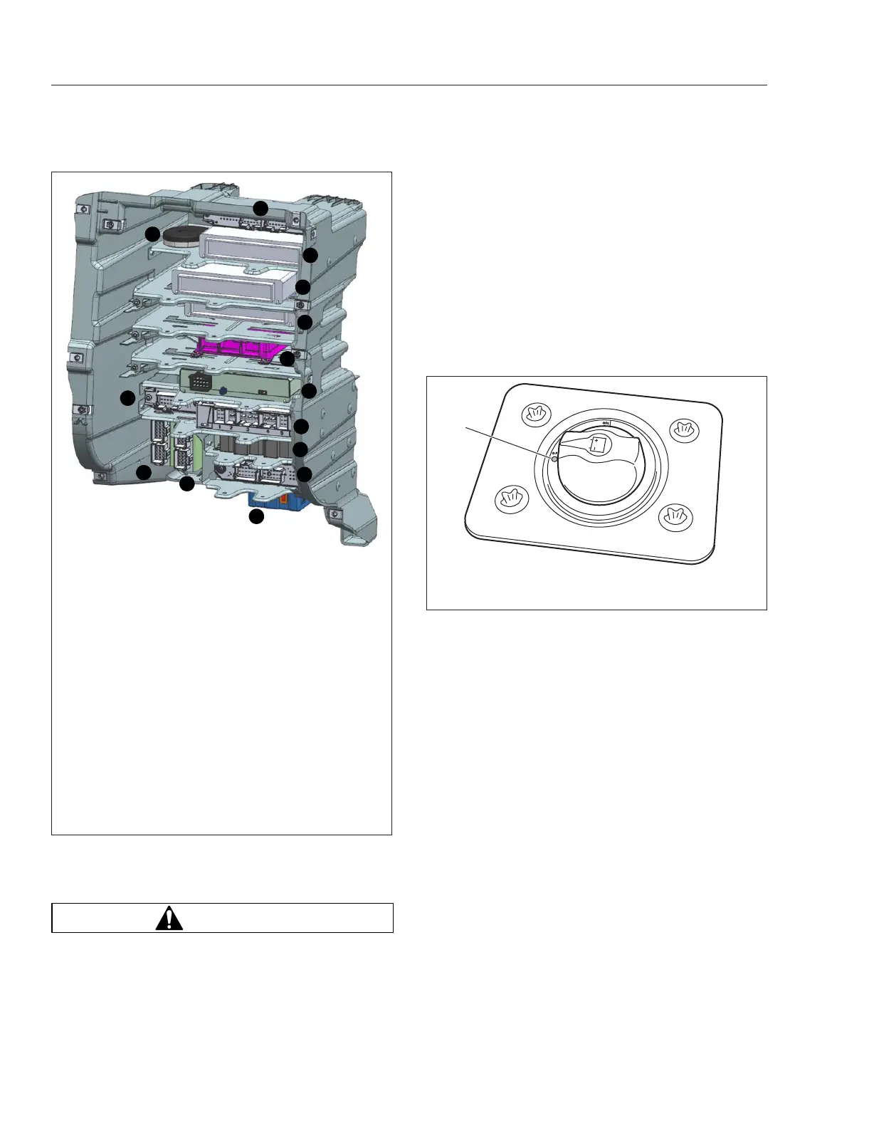
A vehicle in daily use would have the CLDS switch
turned ON. When the CLDS switch is set to ON, a
red LED indicator at the base of the switch selector
illuminates. See
Fig. 11.9.
Turning the CLDS switch OFF minimizes the power
draw on the battery, preserving battery life and the
ability of the vehicle to start after being parked for a
number of days. The CLDs switch should be set to
OFF if the vehicle is going to be parked for more
than three days.
The CLDS may be mounted in a variety of location,
including:
•
inside the cab on the outboard side of the
driver’s seat;
•
behind the cab on the driver’s side;
•
at the battery box.
If the CLDS is turned to the off position while the ve-
hicle is running, the emergency power system will
activate. The powertrain power distribution module
will receive power from the emergency power feed,
but the batteries will not be charging. See the Limp
Home Mode for details about vehicle behavior under
these conditions.
f54631307/25/2016
9
14
1
2
3
4
5
6
7
8
10
11
12
13
NOTE: This figure shows almost all slots filled. In a typi-
cal vehicle, more electronics bay slots would be free.
1. Truck Data Connect Antenna
2. Chassis CAN Starpoint Connector
3. Common Telematics Platform
4. Expansion Module
5. Expansion Module
6. Electronically Controlled Air Suspension (ECAS)
ECU
7. Integrative Predicative Powertrain Control (IPPC)
Module
8. Common Powertrain Controller ECU
9. Antilock Braking System (ABS) ECU
10. Cabin CAN Starpoint Connector
11. Central Gateway
12. Video Radar Decision Unit (VRDU) ECU
13. Expansion Module
14. Powertrain CAN Starpoint Connector
Fig. 11.8, Electronics Bay
f545527a08/14/2020
1
1. LED Indicator Light
Fig. 11.9, Cab Load Disconnect Switch
Electrical System
11.5