Battery Contactor Control Board
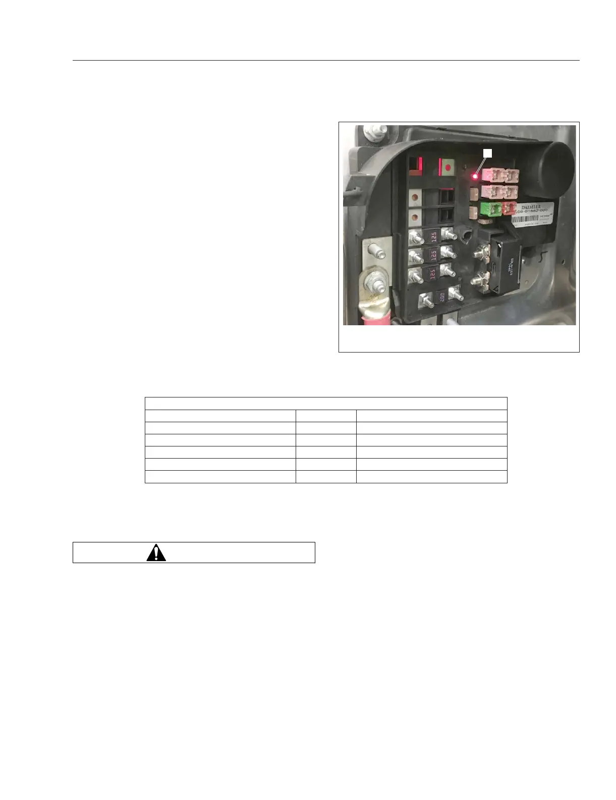
The optional battery contactor control board (CCB) is
designed to cut power to high-current components
when the cab load disconnect switch is in the OFF
position. The battery contactor control board has an
LED that reports the status of the cab load discon-
nect switch. See
Fig. 11.10. Refer to Table 11.2 for
LED status message explanations; this information
will also posted on a label inside the cover of the
battery cable access box (see
Fig. 11.6.)
CLDS LED Status Messages
Description LED Status Message
Solid red ON CLDS ON (normal operation)
Slow flashing red ON CLDS disconnected (error)
Flashing red ON CLDS ON/circuits OFF (error)
Fast flashing red ON CLDS OFF/circuits ON (error)
OFF OFF Power OFF
Table 11.2, CLDS LED Status Messages
Limp Home Mode
WARNING
If limp home mode activates, do not shut down
the engine until the vehicle is out of traffic and in
a safe place. The engine will not be able to be
restarted until the cause of the loss of power is
corrected.
Limp home mode, also known as the emergency
power circuit, is a feature that allows a vehicle to be
moved out of traffic and off the road in the event of a
loss of power.
The emergency power circuit is live even when the
cab load disconnect switch (CLDS) is turned off.
The following is a list of behaviors that could occur
when in limp hope mode:
•
Inoperative switches and lamps.
•
Unresponsive or frozen gauges.
•
Display of warning lamps that indicate low volt-
age and/or ECU faults.
•
Lamps either constantly on or flashing.
•
Windshield wipers on low speed.
The cause of the loss of power will dictate the spe-
cific behaviors that appear. If limp home mode is ac-
tivated due to a microprocessor failure in the sSAM
ECU, gauges will become unresponsive; this in-
cludes dash panel lamps and turn signal indicators.
NOTE: Possible variations in lamp illumination
are noted in parentheses.
f54635408/19/2016
1
1. Cab Load Disconnect Switch Status LED
Fig. 11.10, Battery Cable Access Box (engine side)
Electrical System
11.6