3.
When on the Telephone screen, select OK on
the left-hand steering wheel switch pod to access
Telephone Settings.
4.
Use the Right and Left arrows to navigate from
one telephone setting to another—from contacts
to missed calls for example.
5.
Use the Up and Down arrows in the left-hand
steering wheel switch pod to navigate through
the current Telephone Settings list of choices.
6.
Press OK on the left-hand steering wheel switch
pod to choose an option.
7.
Press the Back left-hand steering wheel switch
pod to return to the main screen.
Analog Instruments
Physical instruments are listed here in alphabetical
order. Some are optional and therefore not found in
every vehicle. Digital instruments and gauges are
described in their ICU section.
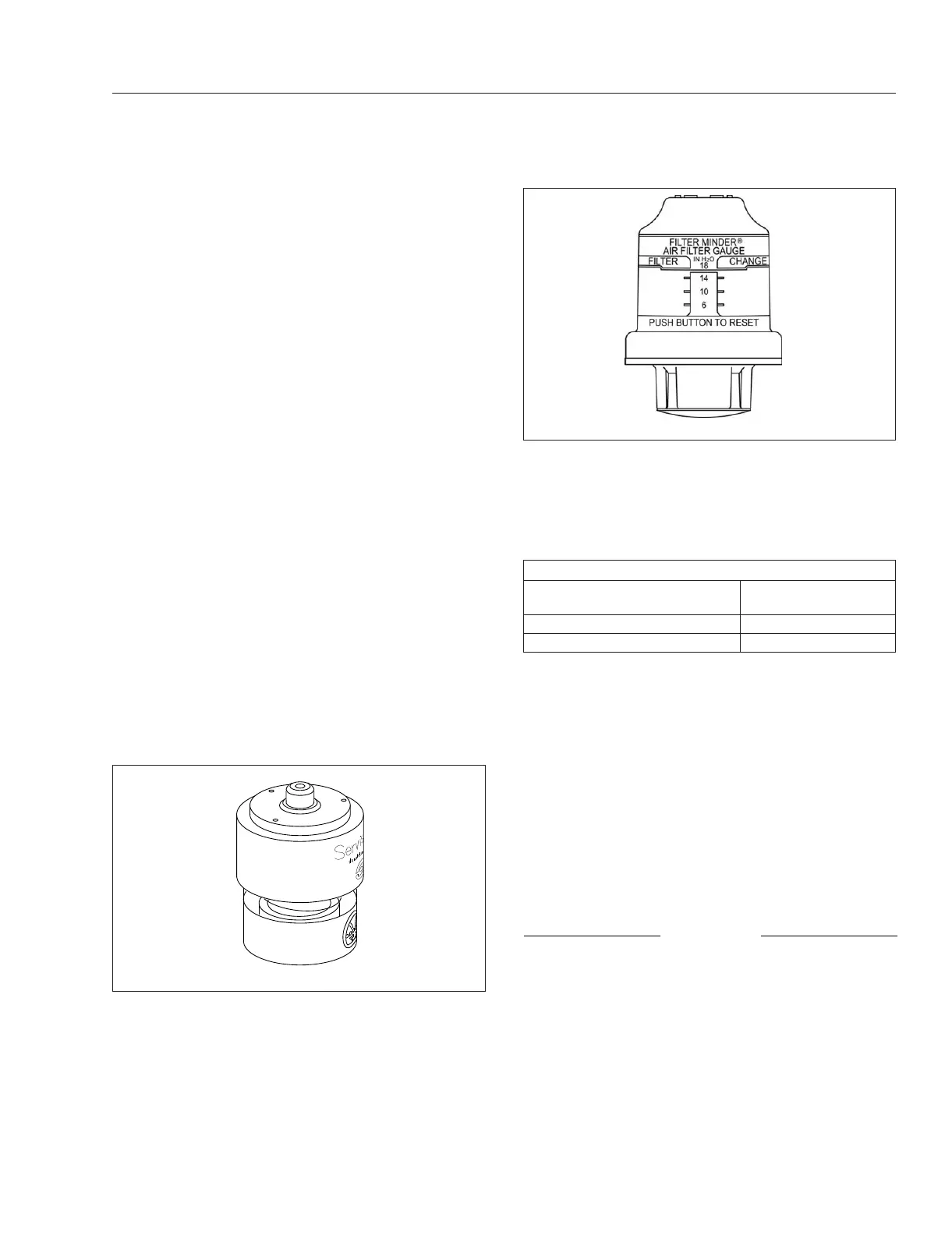
Air Intake Restriction Gauge
The air intake restriction gauge indicates the vacuum
on the engine side of the air cleaner. On standard
installations, it is mounted on the air intake duct in
the engine compartment, and has a go/no-go restric-
tion indicator without graduations. See
Fig. 3.34.As
an option, a graduated indicator (Fig. 3.35) on the air
intake duct or, for easier viewing, a dash-mounted
restriction gauge may be installed.
Air intake restriction vacuum is measured in inches
of water (inH
2
O). For vehicles equipped with a
graduated indicator or a restriction gauge on the
dash, check the gauge with the engine off. If the yel-
low signal stays locked in the red zone once the en-
gine is shut down, or is at or above the values
shown in
Table 3.1, the air cleaner element needs to
be replaced.
Air Intake Maximum Restriction Values (inH
2
O)
Engine Make
GHG14, GHG17, and
GHG21 Engines
Cummins 25
Detroit 18
Table 3.1, Air Intake Maximum Restriction Values
NOTE: Rain or snow can wet the filter and
cause a temporary high reading.
Application Air Pressure Gauge
An application air pressure gauge (Fig. 3.36) regis-
ters the air pressure being used to apply the brakes,
and should be used for reference only. The gauge
will not register air pressure until the foot brake pedal
is depressed or the trailer hand brake is applied.
Coolant Temperature Gauge
NOTICE
A sudden increase in coolant temperature may
indicate engine or cooling system failure. Bring
the vehicle to a safe stop and investigate the
cause to prevent further damage. Do not operate
the engine until the cause has been determined
and corrected.
During normal engine operation, the coolant tem-
perature gauge should read 175 to 195°F (79 to
91°C). If the temperature remains below 160°F
04/08/2005 f090431
Fig. 3.34, Manual-Reset Air Restriction Indicator, Go/
No-Go
02/12/2015 f090514
Fig. 3.35, Air Intake Restriction Indicator, Graduated
Instruments
3.20