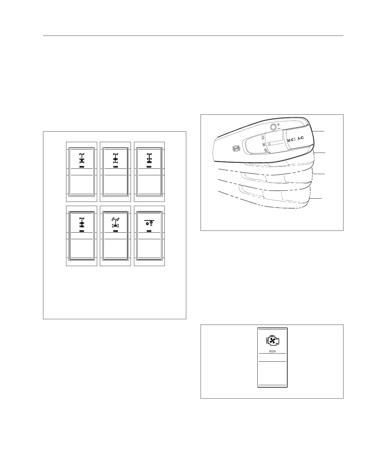
Axle Switches
Some vehicles are equipped with an interaxle differ-
ential lock switch and/or a switch for each driver-
controlled differential lock (DCDL). See
Fig. 4.13.
For more information about differential locks and
using them for traction control, see
Chapter 19 Drive
Axles.
Engine Brake Switches
NOTE: See Chapter 15 Brake Systems for de-
tailed information about engine brake operation.
Whenever vehicle braking is required on good road
conditions, the engine brake may be used in con-
junction with the service brakes. There is no time
limit for operation of the engine brake. However, an
engine brake does not provide the precise control of,
and is not a substitute for, service brakes.
The engine brake control is located on the right-hand
steering-column-mounted lever. At the top position,
the engine brake is off, and at the three lower posi-
tions, the brake is on and the intensity (low, medium,
high) increases with each step down. See
Fig. 4.14
NOTE: Cruise control and safety systems may
activate the engine brake regardless of the lever
position.
Engine Fan Switch
The engine cooling fan can be turned on by the en-
gine fan switch.
To turn the engine fan on, press the upper half of the
switch. The fan will continue to operate for a set
amount of time and then turn off unless the coolant
temperature is high enough to continue fan opera-
tion. To turn the fan off before the set time period
ends, press the lower half of the switch. See
Fig. 4.15.
f61134409/15/2016
DIFF
LOCK
FWD
DIFF
REAR
DIFF
INTR
AXLE
DIFF
LOCK
LIFT
AXLE
LOCK
UNLOCK
LOCK
UNLOCK
LOCK
UNLOCK
LOCK
UNLOCK
LOCK
UNLOCK
LOWER
RAISE
456
123
1. Interaxle Lock Switch
2. Forward Drive Axle Differential Lock Switch
3. Rear Drive Axle Differential Lock Switch
4. Differential Lock Switch, 6X4
5. Differential Lock Switch, 4X2
6. Lift Axle Switch
Fig. 4.13, Axle Switches
f270164a02/17/2017
0
1
2
3
0. Off
1. Low
2. Medium
3. High
Fig. 4.14, Engine Brake Positions
f611405
04/18/2016
ENG
FAN
Fig. 4.15, Engine Fan Switch
Driver Controls
4.8