Do you have a question about the Delphin ProfiMessage and is the answer not in the manual?
Crucial safety guidelines and precautions for device operation to prevent hazards and ensure proper handling.
Specifies the necessary hardware and software requirements for installing and operating Delphin products.
Explains common symbols used throughout the manual for better understanding of warnings and information.
Step-by-step guide for installing necessary software, including DataService Configurator and ProfiSignal.
Instructions for establishing a connection between the PC and the ProfiMessage device via LAN.
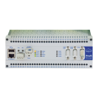
Basic steps required to unpack, power up, and begin using the ProfiMessage device.
Details on configuring basic device settings, selecting devices, and making initial channel configurations.
Information on the device's power input specifications, voltage requirements, and pin assignment.
Overview of LED indicators for power, status, modules, and interfaces like LAN and USB.
Details on COM interface pin assignments (RS-485, RS-232) and CAN interface specifications.
Wiring diagrams and terminal assignments for various I/O modules (AAST, ADFT, ADGT, etc.).
Procedural guide for safely installing and removing I/O modules, including ESD precautions.
Instructions for installing or replacing the internal memory card, emphasizing ESD safety measures.
Steps for installing or replacing the internal battery, including ESD precautions and battery lifespan.
Provides an overview of the configuration and operation section, highlighting key parameters and methods.
Explains how to configure the ProfiMessage device itself, including settings for interfaces and channels.
Details on connecting slave devices to the ProfiMessage system using CAN-bus and Delphin CAN Protocol (DCP).
Explains common settings and dialogue elements applicable across various channel types.
Covers channel-specific settings like validity range, data reduction, formatting, and persistence.
Details on specifying corrections for sensors, including offset and slope adjustments for accurate readings.
Displays dependent channels and events related to a specific channel configuration.
Describes how to select channels as sources or targets in various dialogue windows.
Explains advanced channel selection methods using filtering for efficient searching of configured channels.
Details on trigger functions based on signal edge or level states for event-driven operations.
Option to use source status along with its value for functions, preventing invalid inputs in calculations.
Covers settings related to the System group, including monitoring, LEDs, user management, and network.
Provides information on system resources like CPU usage, memory availability, and operating times.
Details on specifying display backlight brightness and assigning LEDs for status indication.
Manages user access levels (Administrator, Guest, root) and enables user management features.
Configuration of device date, time, and time zone settings, including synchronization options.
Settings for system-wide options, including enabling debugging and anonymous login.
Configuration of network parameters such as hostname, domain, DNS server, and server services.
Describes the configuration process for channels within I/O modules, including software channels and interfaces.
Details configurations at the I/O module level and procedures for adding or deleting module entries.
Information specific to the AMDT I/O module for vibration measurement and its technical specifications.
Configuration options for analogue inputs, dependent on sensor type like voltage, resistance, or current.
Configuration for voltage sensors, including mode, measuring range, and scaling for accurate voltage readings.
Configuration for resistance sensors, covering measuring range and scaling for resistance-based measurements.
Settings for current sensors, including mode, measuring range, and connection types (2-wire, 4-wire).
Specific configuration for 0/4 mA to 20 mA current sensors, including mode and scaling.
Configuration details for resistance thermometer sensors like Pt100, including temperature formats and scaling.
Settings for thermocouple sensors, covering sensor types, measuring ranges, temperature formats, and scaling.
Configuration for pH probes, including sensor type, measuring range, and temperature compensation settings.
Covers advanced settings for analogue inputs, including monitoring, wire break, cycle times, and cold junction settings.
Describes how to create and configure software channels for calculations, functions, and virtual channels.
Software channel that adds values from a source channel, with options for reset and intermediate value generation.
Software channel that registers active periods, retaining value across scale changes and supporting reset.
Calculates the ratio of value difference to time difference, supporting time base and trigger settings.
Placeholder for Event functionality description.
Software channel functioning as a hardware flip-flop, with options for JK, RS, D, and Latch modes.
Monitors source channel against thresholds, generating logic signals based on alarm conditions like overrun or underrun.
Generates square signals with variable frequency and pulse-pause ratio in free-running or synchronous modes.
Calculates the area below a curve by summing values over time, with cyclic, adaptive, and reset options.
Allows grouping related or interdependent channels, facilitating organization and management.
Enables additional conversion of channel values using tables, with modes like offset, quadratic, and interpolation.
Links digital channels logically using boolean functions like AND, OR, NOT, XOR, and XNOR.
Provides control options for processes via DataService Configurator or ProfiSignal applications.
Calculates the average of source values, supporting moving and block averaging methods.
Enables continuous control of process variables using P, I, PI, PD, and PID controllers.
Introduces fundamental concepts of control technology to aid understanding of PID controllers.
Defines key variables and parameters used in control loops, such as reference, manipulated, and control variables.
Explains control paths, their categories (with/without compensation), and system properties like P, T1, and dead time.
Describes different types of continuous controllers (P, I, PI, PD, PID) and their operational characteristics.
Provides methods for determining controller parameters, including guidelines for control paths with equalisation.
Details on configuring PID controllers through specific tabs like Main settings, Controller 1, and Controller 2.
Generates square signals with variable frequency and pulse-pause ratio, controlled by source or fixed values.
Allows calculation of mathematical formulas using variables, constants, and expressions.
Monitors boolean output signals to generate common alarms, with latching and reset options.
Transmits values with delay, allowing specification of source, number of measurements, and trigger conditions.
Enables the device to function as a programmer, defining conditional procedures via setpoint tables.
Evaluates sources using statistical functions like min/max, variance, and RMS, with options for block evaluation.
Allows suppression of status messages and control of other outputs based on specific statuses.
Generates specific statuses for testing system reactions, triggered immediately or by a channel.
Monitors the source and becomes active when a specified status is met.
Functionality for timing events, starting and stopping based on signal levels or edges, with reset options.
Displays system information such as CPU load, memory usage, and operating times.
Filters small signals, relaying values only if they exceed a set tolerance from the previous output.
Generates logic signals based on analogue source signals, active after specific trigger events like edges or levels.
Configuration of device date, time, and time systems (UTC, Unix), and tracking daylight saving time.
Triggers specific events at specified times, generating one-off or repeat alarms.
Counts events based on upward, downward, or reset triggers, with options for intermediate values and value output.
Changes the timing of digital source signals, allowing pickup or dropout delay for signal processing.
Information on configuring memory groups and enabling data export to a USB memory stick.
Illustrates connection examples for various sensors, including voltage, current, and thermocouple types.
Details on connecting actuators to analogue and digital outputs, including load resistance and voltage requirements.
Explains the galvanic isolation properties of the device's inputs and interfaces for electrical safety.
Describes the PE terminal's function as a ground connection for the device and its internal connections.
Discusses the causes and effects of earth loops in sensor and computer connections, and interference issues.
Recommendations for using shielded cables to prevent disruption of measurement signals by electromagnetic fields.
Information on ESD protection measures for inputs, including the use of earth terminals.
Explains potential differences that can occur between reference potentials of multiple-sensor signals.
General technical specifications for the main device, including dimensions, weight, material, and processor.
Technical specifications for AAST, ADGT, ADIT, and ADVT I/O modules, covering analogue inputs and outputs.
Technical specifications for DIOT, IOIT, and OTPT I/O modules, detailing digital inputs and outputs.
Technical specifications for the ADFT I/O module, covering analogue inputs, outputs, and digital I/O.
Technical specifications for the AMDT I/O module, focusing on analogue inputs/outputs and digital I/O.
Information on the hardware of the AMDT I/O module, including its design and physical setup.
Guidelines for planning and designing systems involving the AMDT I/O module, considering setup rules and analogue inputs.
Details on the industrial connector panel for the AMDT I/O module, showing analogue inputs and outputs.
Layout of the laboratory connector panel for the AMDT I/O module, illustrating input/output connections.
Block diagram illustrating the hardware architecture of the AMDT I/O module and signal flow.
Comprehensive technical specifications for the AMDT I/O module's hardware, including isolation and input/output capabilities.
Details on the galvanic isolation properties of the AMDT I/O module's inputs and outputs.
Specifications for analogue inputs of the AMDT I/O module, covering ranges, sampling, resolution, and precision.
Specifications for analogue outputs of the AMDT I/O module, including output range, resolution, and signal error.
Specifications for digital inputs of the AMDT I/O module, covering potential isolation and sampling rates.
Specifications for counter functionality on digital inputs, including pulse counting and frequency measurement precision.
Specifications for digital outputs of the AMDT I/O module, including switching voltage, current, and isolation.
Describes the different operating modes for the I/O module, including batch recording and continuous recording.
Details the batch recording mode for I/O modules, focusing on data acquisition and transfer sequence.
Explains the continuous recording mode, where data processing occurs simultaneously with sampling.
Allows replacement of real signals with demo signals for testing, offering various signal and modulation types.
Instructions for synchronizing two AMDT I/O modules for simultaneous data acquisition and triggering.
Covers settings for triggering events and recording data, including software/hardware triggers and recording depth.
Explains options for redundant trigger sources to ensure continuous recording in case of signal failure.
Describes how vibration signals are saved as time signals, supporting variable history and digital filters.
Details digital filter types (low-pass, band-pass) and their settings for processing acquired signals.
Explains the digital integrator's function for numerical integration of vibration signals.
Covers FFT analysis and frequency spectrum computation, including algorithms and setting frequency ranges.
Describes calculation of characteristic vibration values from time signals and frequency spectra.
Defines how the DSP finds and delivers maximum and minimum values from the time signal.
Explains calculation of the peak-to-peak value, representing the difference between highest positive and negative amplitudes.
Defines the arithmetical average calculation of the time signal, representing the steady or DC component.
Explains the calculation of the True Root Mean Square (TRMS) value for the time signal.
Describes finding the largest amplitude in the frequency spectrum and delivering its frequency.
Details finding the largest amplitude in the frequency spectrum and its corresponding value.
Covers phase angle measurement for low frequencies/rotation speeds, using digital pulses for reference.
Determines amplitude of vibration components (1X, 2X, 3X) using cyclical digital pulses for frequency reference.
Calculates phase angles for vibration components using frequency spectrum and rotation speed factor.
Determines signal periods, frequency, and rotation speed from input signals, with configurable limits.
Performs vectoral addition of amplitude values from two consecutive channels to find the maximum.
Calculates the arithmetical average of amplitude values from two consecutive channels.
Finds the peak amplitude frequency within a specified band of the frequency spectrum.
Finds the peak amplitude within a specified band of the frequency spectrum.
Calculates the RMS value using lines within a narrow frequency band of the spectrum.
Calculates a weighted sum for all quadratic lines of a frequency spectrum.
Calculates a weighted sum excluding harmonic components and optional definable components.
Measures current frequencies and rotation speed on equipment, determining rotation speed for frequency spectrum analysis.
Explains phase angle measurement for low frequencies/rotation speeds and provides definitions.
Monitors characteristic values against thresholds, allowing logical linking to digital outputs.
Details using DataService Configurator for hierarchical display and configuration of system components.
Covers I/O module settings effective for all analogue inputs, focusing on operating mode, triggering, and recording.
Explains how measurement data is recorded and displayed, including status information and block counters.
Details configuration and settings for analogue inputs, including active status, additional settings, and main settings.
Guides on configuring FFT/spectrum settings, including window functions, compression, and averaging.
Steps for adding or deleting characteristic value channels from analogue inputs.
Configuration for analogue outputs, covering output range, scaling, and source selection.
Configuration for digital inputs, including inversion and settings for counters.
Settings for counter functionality, including measurement unit and frequency measuring modes.
Configuration for digital outputs, including source selection and inversion.
Overview of ProfiSignal software for data logging, analysis, and visualization, showing example diagrams.
Procedure for updating the device firmware using an internet browser via the Ethernet interface.
Methods for copying acquired data from device memory to a USB stick without PC connection.
Steps for direct data transfer to a USB stick without prior configuration on the device.
Guides on configuring data transfer settings via DataService Configurator, including save modes and XML format.
Official ISO 9001 certificate issued by Lloyd's Register Quality Assurance.
EC Declaration of Conformity, confirming compliance with relevant EU directives.
| Brand | Delphin |
|---|---|
| Model | ProfiMessage |
| Category | Test Equipment |
| Language | English |