4 Basic Instructions
DVP-20PM Application Manual
4-10
Instruction
code
Function Applicable model
20PM
DCNT
32-bit counter
C-K C200, C204, C208~C255, K-2,147,483,648~K2,147,483,647
Operand
C-D C200, C204, C208~C255, D0~D9,999
Explanation
DCNT is an instruction which is used to enable the 32-bit counters C200~C255.
C221~C2255 are general up/down counters. When the counter coil specified
by the instruction DCNT is turned from OFF to ON, the counter value increases
or decreases by one according to the setting of M1200~M1234.
Example
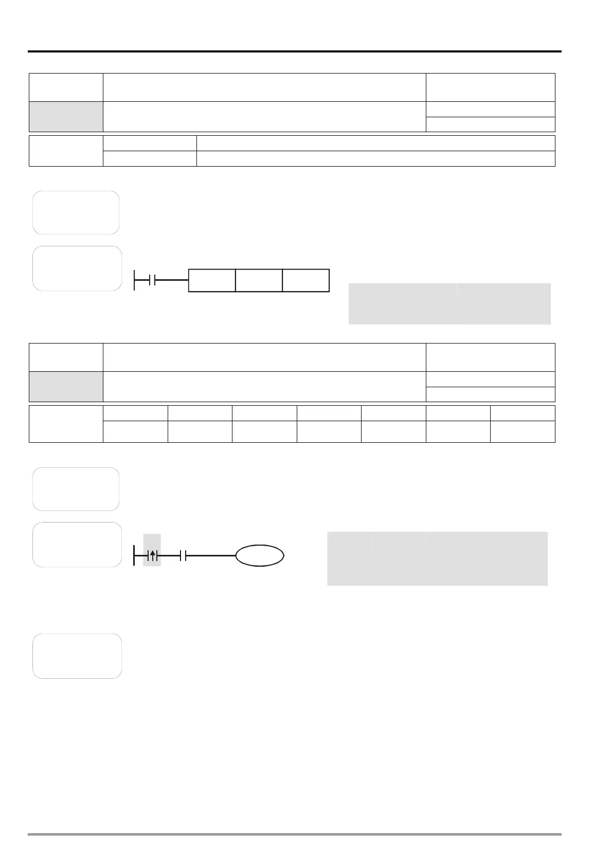
Ladder diagram:
M0
C254DCNT
K1000
Instruction code: Description:
LD M0 Loading the Form
A contact M0
DCNT C254 K1000
The setting value
in the counter
C254 is K1000.
Instruction
code
Function Applicable model
20PM
LDP
Starting rising-edge detection
X0~X377 Y0~Y377 M0~M4,095 S0~S1,023 T0~T255 C0~C255 D0~D9,999
Operand
-
Explanation
The usage of LDP is similar to that of LD, but the action of LDP is different from
that of LD. LDP reserves the present contents, and stores the state of the rising
edge-triggered contact specified to an accumulation register.
Example
Ladder diagram:
X0 X1
Y1
Instruction code: Description:
LDP
X0 Starting the detection
of the state of the rising
edge-triggered contact
X0
AND X1 Connecting the Form A
contact X1 in series
OUT Y1 Driving the coil Y1
Additional
remark
If
Please refer to the specifications for the model used for more information about
the operand ranges which can be used.
the state of a rising edge-triggered contact in a DVP-20PM series motion
controller is ON before the DVP-20PM series motion controller is powered, it is
TRUE after the DVP-20PM series motion controller is powered.

 Loading...


