11 CANopen Communication Card
CR#n07~CR#n08: Product type
[Description]
The control registers are used to display the product type of an ASDA-A2 servo drive.
Data type: Double word
CR#n09: CANopen node communication status
[Description]
The control register is used to display a node communication status in a CANopen network. Please
refer to the table below for more information.
Status Value
Disconnected H’1
Connected H’2
Operation mode H’5
Error H’6
Reset H’7
CR#n10: Emergency error code
[Description]
The control register is used to display an error code defined by a CANopen protocol when an error
occurs in a certain node.
CR#n11~CR#n12: Manufacturer’s error code
[Description]
The control registers are used to display an error code defined by a manufacturer when an error occurs
in an ASDA-A2 series servo drive. Please refer to Delta ASDA-A2 User Manual for more information
about error codes.
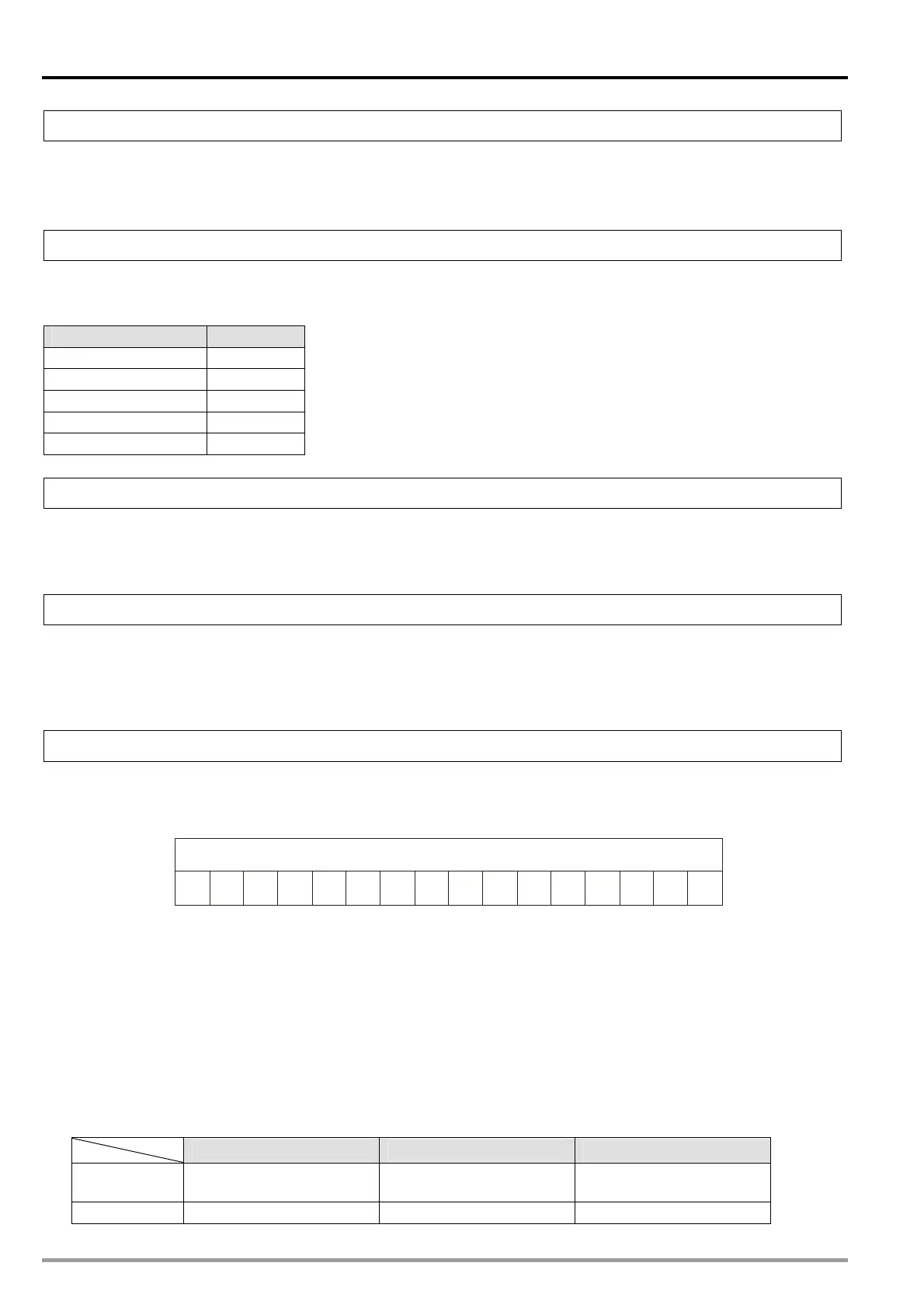
CR#n20: Servo drive status
[Description]
The value in the control register indicates the present status of an ASDA-A2 series servo drive. Please
refer to the table below for more information.
RS
XSO
FT
0123456789101
1
1
141
QS
WR
X
X
TR
OM
OM
X
X
Status word
Bit
X
RM
OM
RS: The servo drive is ready. After the initialization of the servo drive is completed, the bit will be 1.
SO: The servo drive is ON. The bit will be 1 if the servo drive is ON.
FT: It is an error flag. If an error occurs in the servo drive, the bit will be 1.
QS: If the bit is 1, the servo drive can be stopped urgently.
WR: It is a warning flag. If the servo drive sends a warning message, the bit will be 1.
RM: If the bit is 1, remote monitoring can be executed.
TR: If the execution of a motion command is completed, the bit will be 1.
OM [14:12]: The bits indicate the statuses of motion modes. Please see the table below for more
information.
Profile position mode Homing mode Interpolation mode
OM [12]
A target position has
been set successfully.
A homing mode is being
executed.
An interpolation mode is
being executed.
OM [13] Following error Homing error X
DVP-20PM Application Manual
11-10

 Loading...


