• Do not use the test leads if the insulation is
damaged or if metal is exposed.
• To avoid electrical shock, do not touch the test
leads, tips, or the circuit being tested.
• Choose the proper range and function for the
measurement. Do not try voltage or current mea-
surements that may exceed the rated capacity.
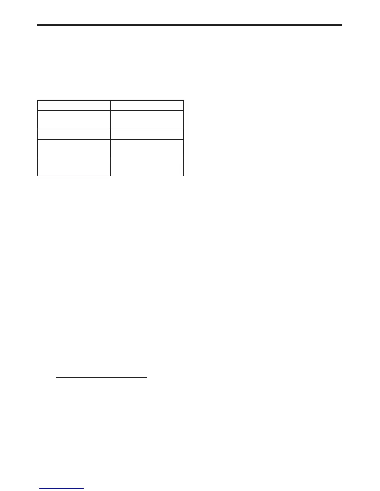
• Do not exceed the limits shown in the table below:
FUNCTION INPUT LIMIT
Volts 0 - 500 peak volts AC
0 - 500 volts DC
Ohms (resistance)* 0 - 1.12 megohms
Frequency Measured
Frequency Generated
0-10kHz
Temperature -58 - 1100°F
-50 - 600°C
* Ohms cannot be measured if voltage is present.
Ohms can be measured only in a non-powered
circuit.
• Voltage between any terminal and ground must
not exceed 500v DC or 500v peak AC.
• Use caution when measuring voltage above 25v
DC or 25v AC.
• The circuit being tested must be protected by a
10A fuse or circuit breaker.
• Use the low current shunt to measure circuits up
to 10A. Use the high current clamp to measure
circuits exceeding 10A.
• When testing for the presence of voltage or cur-
rent, make sure the meter is functioning cor-
rectly. Take a reading of a known voltage or
current before accepting a zero reading.
• When measuring current, connect the meter in
series with the load.
• Disconnect the live test lead before disconnecting
the common test lead.
• When using the meter function, keep the
DRBIIIt away from spark plug or coil wires to
avoid measuring error from outside interference.
4.3 WARNINGS AND CAUTIONS
4.3.1 ROAD TEST WARNINGS
Some complaints will require a test drive as part
of the repair verification procedure. The purpose of
the test drive is to try to duplicate the diagnostic
code or symptom condition.
CAUTION: Before road testing a vehicle, be
sure that all components are reassembled.
During the test drive, do not try to read the
DRBIIIT screen while in motion. Do not hang
the DRBIIIT from the rear view mirror or
operate it yourself. Have an assistant
available to operate the DRBIIIT.
4.3.2 VEHICLE DAMAGE CAUTIONS
Before disconnecting any control module, make
sure the ignition is off. Failure to do so could
damage the module.
When testing voltage or continuity at any control
module, use the terminal side (not the wire end) of
the connector. Do not probe a wire through the
insulation; this will damage it and eventually cause
it to fail because of corrosion.
Be careful when performing electrical tests so as
to prevent accidental shorting of terminals. Such
mistakes can damage fuses or components. Also, a
second DTC could be set, making diagnosis of the
original problem more difficult.
5.0 REQUIRED TOOLS AND
EQUIPMENT
DRBIIIt (diagnostic read-out box) scan tool
Evaporative System Diagnostic Kit #6917
fuel filler adapter #8382
fuel pressure adapter (C-6631) or #6539
fuel pressure kit (C-4799-B) or #5069
fuel release hose (C-4799-1)
Min Air flow fitting #6714
Pinout Box (Miller #8815)
jumper wires
ohmmeter
oscilloscope
vacuum gauge
voltmeter
12 volt test light minimum 25 ohms resistance
with probe #6801
CAUTION: A 12 volt test light should not be
used for the following circuits, damage to the
powertrain controller will occur.
• 5 Volt Supply
• J1850 PCI Bus
• CKP Sensor Signal
• CMP Sensor Signal
• Vehicle Speed Sensor Signal
• O2 Sensor Signal
15
GENERAL INFORMATION

 Loading...


