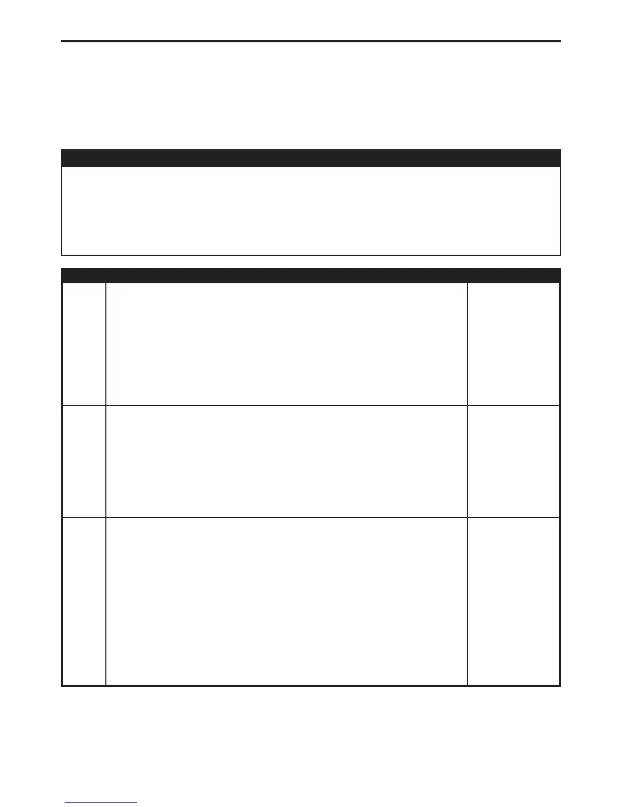
Symptom:
*NO MANUAL AUTOSTICK OPERATION
POSSIBLE CAUSES
AUTOSTICKt DOWNSHIFT SENSE CIRCUIT OPEN
AUTOSTICKt GROUND CIRCUIT OPEN
AUTOSTICKt UPSHIFT SENSE CIRCUIT OPEN
FUSED IGNITION SWITCH OUTPUT CIRCUIT OPEN
PCM - AUTOSTICKt
TEST ACTION APPLICABILITY
1 Turn the ignition off to the lock position.
Disconnect the AutoStickt Switch harness connector.
Note: Check connectors - Clean/repair as necessary.
Ignition on, engine not running.
Measure the voltage of the Fused Ignition Switch Output circuit in the AutoStickt
Switch harness connector.
Is the voltage above 10.0 volts?
All
Yes → Go To 2
No → Repair the Fused Ignition Switch Output circuit for an open.
2 Turn the ignition off to the lock position.
Disconnect the AutoStickt Switch harness connector.
Note: Check connectors - Clean/repair as necessary.
Measure the resistance between ground and the AutoStickt Ground circuit at the
AutoStickt harness connector.
Is the resistance above 5.0 ohms?
All
Yes → Repair the AutoStickt Ground circuit for an open.
No → Go To 3
3 Turn the ignition off to the lock position.
Disconnect the PCM harness connector.
Disconnect the AutoStickt Switch harness connector.
Note: Check connectors - Clean/repair as necessary.
CAUTION: DO NOT PROBE THE PCM HARNESS CONNECTORS. PROBING
THE PCM HARNESS CONNECTORS WILL DAMAGE THE PCM TERMI-
NALS RESULTING IN POOR TERMINAL TO PIN CONNECTION. INSTALL
MILLER SPECIAL TOOL #8815 TO PERFORM DIAGNOSIS.
Measure the resistance of the Upshift Sense circuit between the Pinout Box and the
AutoStickt Switch harness connector.
Is the resistance above 5.0 ohms?
All
Yes → Repair the AutoStickt Upshift Sense circuit for an open.
No → Go To 4
173
TRANSMISSION - NGC

 Loading...


