for inspection or testing purposes. These systems,
when fully charged contain fluid at high pressure.
Before disconnecting any hydraulic tubes, hoses
or fittings, be sure that the system is fully depres-
surized.
When servicing a vehicle, always wear eye pro-
tection and remove any metal jewelry such as
watchbands or bracelets that might make an inad-
vertent electrical contact.
When diagnosing a Transmission system prob-
lem, it is important to follow approved procedures
where applicable. These procedures can be found in
the service information. Following these proce-
dures is very important to the safety of individuals
performing diagnostic tests.
4.2.2 VEHICLE PREPARATION FOR
TESTING
Make sure the vehicle being tested has a fully
charged battery. If it does not, false diagnostic
DTC’s or error messages may occur. It is extremely
important that accurate shift lever position data be
available to the PCM. The accuracy of any DTC
found in memory is doubtful unless the Shift Lever
Test, performed on the DRBIIIt Scan Tool, passes
without failure.
4.2.3 SERVICING SUB-ASSEMBLIES
Some components of the Transmission system
are intended to be serviced in assembly only. At-
tempting to remove or repair certain system sub-
components may result in personal injury and/or
improper system operation. Only those compo-
nents with approved repair and installation proce-
dures in the service information should be ser-
viced.
4.2.4 DRBIIIT SAFETY INFORMATION
WARNING: EXCEEDING THE LIMITS OF THE
DRBIIIT MULTIMETER IS DANGEROUS. IT
CAN EXPOSE YOU TO SERIOUS OR
POSSIBLY FATAL INJURY. CAREFULLY
READ AND UNDERSTAND THE CAUTIONS
AND THE SPECIFICATION LIMITS.
• Follow the vehicle manufacturer’s service speci-
fications at all times.
• Do not use the DRBIIIt if it has been damaged.
• Do not use the test leads if the insulation is
damaged or if metal is exposed.
• To avoid electrical shock, do not touch the test
leads, tips, or the circuit being tested.
• Choose the proper range and function for the
measurement. Do not try voltage or current
measurements that may exceed the rated capac-
ity.
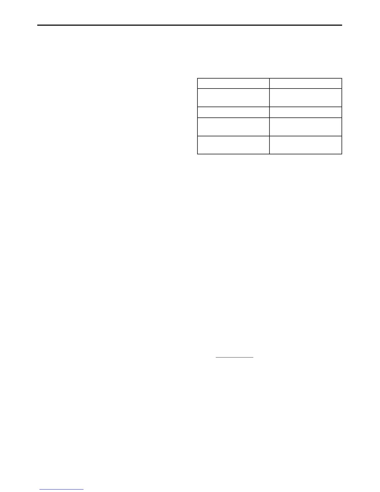
• Do not exceed the limits shown in the table.
FUNCTION INPUT LIMIT
Volts 0 - 500 volts peak AC
0 - 500 volts DC
Ohms (resistance)* 0 - 1.12 megohms
Frequency Measured
Frequency Generated
0-10kHz
Temperature -58 - 1100°F
-50 - 600°C
*Ohms cannot be measured if voltage is present.
Ohms can be measured only in a non-powered
circuit.
• Voltage between any terminal and ground must
not exceed 500v DC or 500v peak AC.
• Use caution when measuring voltage above 25v
DC or 25v AC.
• The circuit being tested must be protected by a
10A fuse or circuit breaker.
• Use the low current shunt to measure circuits up
to 10A. Use the high current clamp to measure
circuits exceeds 10A.
• When testing for the presence of voltage or
current, make sure the meter is functioning
correctly. Take a reading of a known voltage or
current before accepting a zero reading.
• When measuring current, connect the meter in
series with the load.
• Disconnect the live test lead before disconnect-
ing the common test lead.
• When using the meter function, keep the
DRBIIIt away from spark plug or coil wires to
avoid measuring error from outside interference.
4.3 WARNINGS
4.3.1 VEHICLE DAMAGE WARNINGS
Before disconnecting any control module, make
sure the ignition is “lock” position. Failure to do so
could damage the module.
When testing voltage or continuity at any control
module, use the terminal side (not the wire end) of
the connector. Do not probe a wire through the
insulation; this will damage it and eventually
cause it to fail because of corrosion.
Be careful when performing electrical tests so as
to prevent accidental shorting of terminals. Such
mistakes can damage fuses or components. Also, a
21
GENERAL INFORMATION

 Loading...


