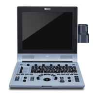
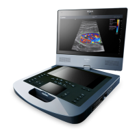
U60 Diagnostic Ultrasound System User Manual System Control
- 29 -
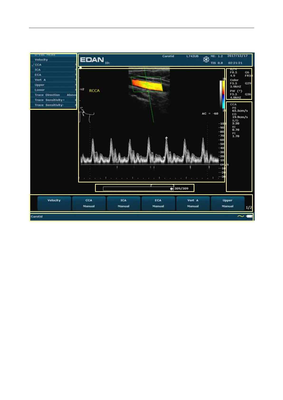
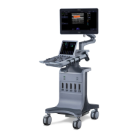
5.3. Screen Layout
Figure 5-1 Monitor Display
①Information Field:
Manufacturer logo, Institution/Hospital name, Patient name, Patient ID, Current examination
type, Probe model, Probe frequency, “Freeze” icon, MI, TI, System date and time, etc.
②Image Field:
Ultrasound image (B/Color/PDI/PW/CW/M mode), Gray map bar, Color map bar, Depth scale,
Focus mark, Sample line of PW/M mode, Sample volume of PW mode, Scan area window of
Color mode (also referred to as the region of interest, or ROI), Needle guide line, Probe scan
direction mark, Comments (texts or arrows), Body marks, Measurement caliper, TGC curve,
etc.
③Menu Field:
Image control menus /control program menus. The content of menus depends on system
status.
④Measurement Results Field:
The field displays the measurement and calculation items and results in different rows.
⑤Parameter Field:
It displays the principal image parameters of each mode. Parameters of the currently active
mode are marked with “*” symbols. Parameters of B mode: Freq, Gain, Depth, and Frame
Rate; Parameters of Color /PW/CW mode: Freq, Gain, and PRF.
⑥CINE Review Progress Bar
⑦
E
qu
ip
ot
en
tia
l
③
②
P
ull
E
qu
ip
ot
en
tia
l
ter
mi
na
l
R
ea
r
⑧
E
qu
ip
ot
en
tia
l
③
②
P
ull
E
qu
ip
ot
en
tia
l
ter
mi
na
l
R
ea
⑥
E
qu
ip
ot
en
tia
l
③
②
P
ull
E
qu
ip
ot
en
tia
l
ter
mi
na
l
R
ea
r
pa
ne
l