Page 10 • 700120S • ENTRON Controls, LLC.
1.1 STANDARD FEATURES (All Models)
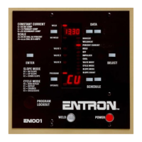
DIGITAL PHASE SHIFT CURRENT CONTROL – Varies the output waveform duty cycle
from 0% to 99%, adjustable in 1% steps by means of Front Panel push buttons and direct
reading LED displays.
FUNCTION TIMING – Control uses Front Panel push buttons and direct reading LED displays
to program parameter timing in 1 cycle steps. Timing of SQUEEZE, HOLD, and OFF are
achieved by counting each cycle of the line current directly. This method of timing allows this
control to be used on either 50 Hz or 60 Hz power without special adjustments.
NO ADJUSTMENT is required for timing to change from 60 to 50 Hz operation.
OPERATING CONDITIONS – Temperature Range: 0°C to 70°C (32°F to 158°F).
POWER SUPPLY MONITORING – Control monitors VCC power supply and, whenever
this voltage goes below safe operating range, the message
d.o.u.n.d.o.u.n.
d.o.u.n.d.o.u.n.
d.o.u.n. will be displayed on DATA
display. After this condition, control must be reset by activating Emergency Stop input or by
reapplying the power to the control.
PRESSURE SWITCH FIRING – Terminal Strip connection which allows the control to be
initiated from a Pressure Switch closure. Remove the jumper from TS1-PS1 and TS1-GND and
connect Pressure Switch leads. Pressure Switch is not furnished with control.
EMERGENCY STOP – Terminal Strip connection which allows all control functions to be
reset upon opening of the Emergency Stop Switch. After an Emergency Stop, the control will
not re-initiate automatically upon release of the switch. The control must be re-initiated
through the initiation circuits. The display will be flashing
E.S.E.S.
E.S.E.S.
E.S. when TS1-ES1 is open. Remove
the jumper from TS1-ES1 and TS1-GND and install a normally closed switch. Emergency Stop
Switch is not furnished with control.
VALVE CONTROL TRANSFORMER – Provides the necessary voltage for powering the
welding machine solenoid valve(s). Input voltage may be either 240 VAC or 480 VAC (see
Wiring Diagram). Valve transformer output is 115 VAC (optional low voltage transformer for
certain operations provides a 24/48 VAC output). A 50 VA transformer is provided in “S”
Cabinets, and 150 VA transformer is standard in “T/D”, “C” and NEMA enclosures (250 VA or
500 VA transformers optional).
This control may be configured for external valve power. See Section 4.3 for Terminal Strip
(TS1) external valve power connection.
When external valve power is used, 24-240 VAC or 24 VDC, valve transformer
must be disconnected at TS3-VL1 and TS3-VL2. Caution must be used to
properly insulate the wires from T3-X1 and T3-X2 leads after removing from TS3.
NOTICE
CAUTION
NOTICE

 Loading...