Page 42 • 700120S • ENTRON Controls, LLC.
5.0 INTRODUCTION TO DATA PROGRAMMING
The EN1000 or EN1001 Control is capable of storing
and accessing up to 50 unique welding schedules. This
makes the EN1000 or EN1001 particularly suitable
for complex welding operations, as well as automated
machinery. Programming allows the operator to enter
or change parameters of weld schedules and the
subsequent storing of those parameters in non-volatile
memory. See Appendix I for programming worksheets.
Basically, programming only requires selecting the
function to be programmed (or modified), changing
the data (with DATA display and push buttons)
applicable to that function, and then entering the
desired parameters into memory. For more detailed
information about programming, see Appendix B,
Section B-1.0.
5.1 GENERAL PROGRAMMING
1. Press and release the PROGRAM/OPERATE push button. The PROGRAM LED will
light up and the OPERATE LED will turn off. Only in the PROGRAM mode does the
control allow changes to existing data or entering new data. If an optional PROGRAM
LOCKOUT key switch is installed, see Section 5.2.
2. Select the schedule to be entered or modified by using the SCHEDULE push buttons
until the desired schedule number appears in the SCHEDULE display. The left push button
increments the display by ten, and the right push button increments the display by one.
When the maximum number is reached for either digit, that digit resets to zero.
3. Press the SELECT push button to reach the required function. Pressing and holding
the SELECT push button momentarily will move to the previous parameter. The FUNCTION
indicator LEDs show which function may be entered or modified, and the DATA display
shows the data stored in that function. If the SELECT push button is pressed again, the
FUNCTION indicator LED will advance to the next function.
When the FUNCTION indicator LED is advanced one position past the SLOPE COUNT
function, all FUNCTION indicator LEDs will be off and the DATA display will show
EFEF
EFEF
EF. This
indicates that the control is in the EXTENDED FUNCTION mode and the EXTENDED
FUNCTIONS can now be altered or viewed (see Section 5.4).
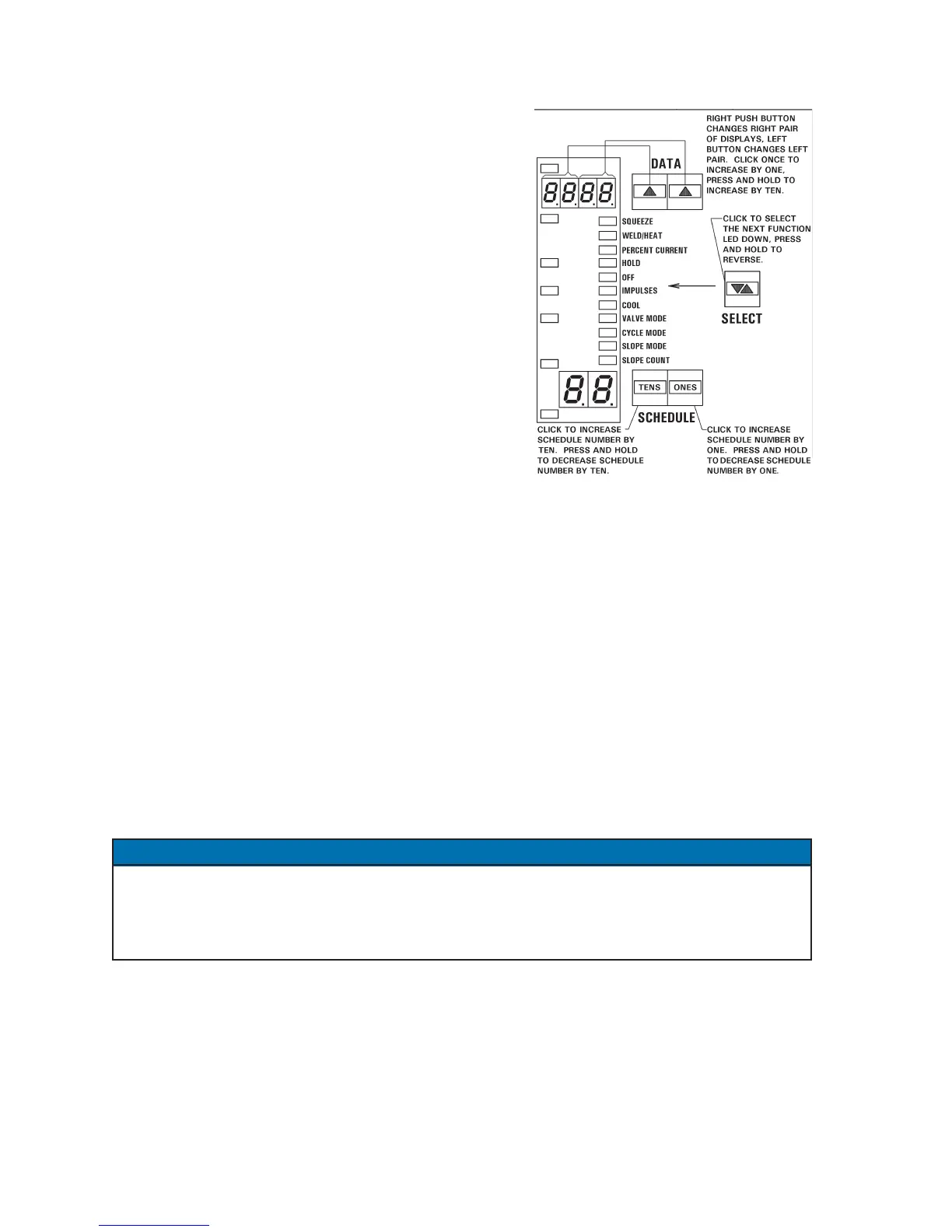
4. Use the DATA push buttons to change data. The left button increments the data by ten,
and the right button increments the data by one. When either digit reaches the maximum,
that digit resets to zero. For parameters which allow programming of all four digits, the
right button affects the two right-hand digits – click to increment by one; press and hold to
increment by ten. The left button affects the two left-hand digits – click to increment by
100; press and hold to increment by 1000.
5. Press the ENTER push button to store data from the DATA display into non-volatile
memory. As ENTER is pressed, the DATA display will blink and then remain steady.
Figure 5-1. Four-digit DATA display
NOTICE

 Loading...
