Page 36 • 700120S • ENTRON Controls, LLC.
4.4 INITIATION
The EN1000 and EN1001
Controls are equipped with
four weld initiation inputs
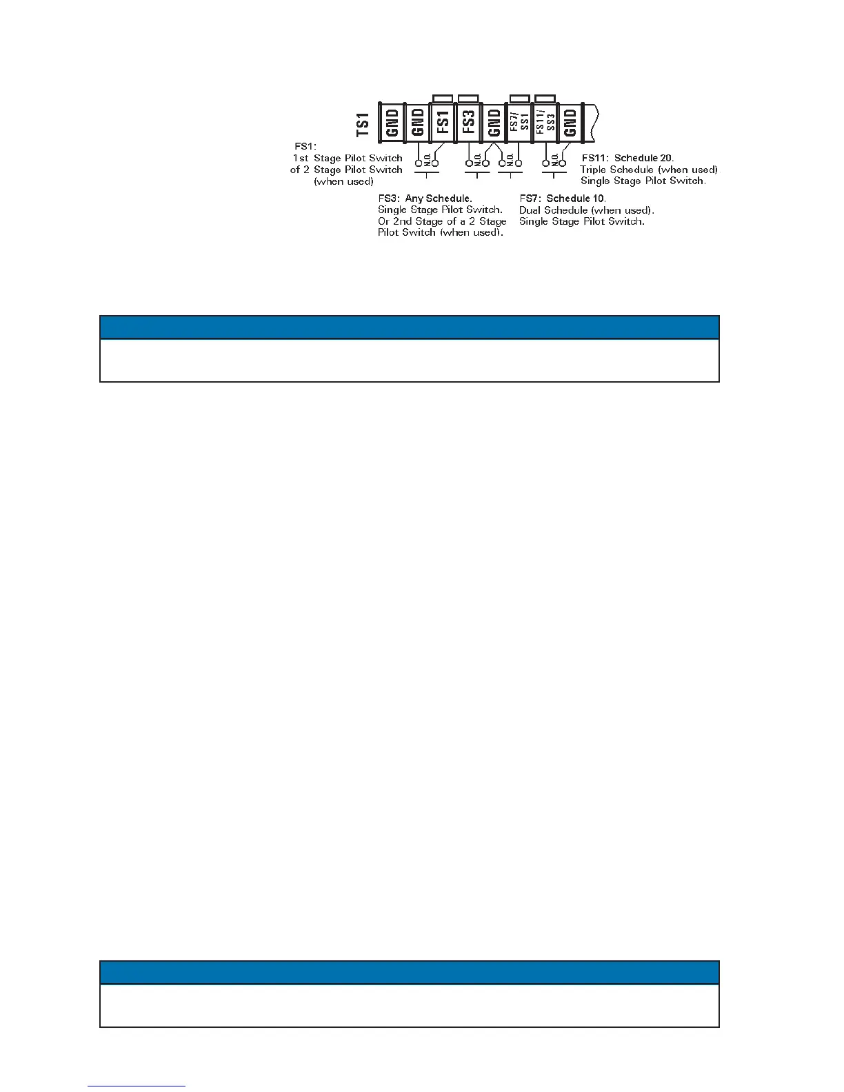
– FS1, FS3, FS7 and FS11
– shown in Figure 4-7 (see
also Section 5.4.3), and
provide two basic weld
initiations: Single Stage
Pilot and Two Stage Pilot.
For more information about routing and wiring of initiation wires, see Section 4.6.
This control can be programmed to BEAT operation by programming
b.E.b.E.
b.E.b.E.
b.E. parameter in
EXTENDED FUNCTIONS (see Section 5.4.8). Several modes are available.
4.4.1 SINGLE STAGE PILOT INITIATION
Connect the Pilot Switch between TS1-FS3 and TS1-GND. Once the control is initiated, the
switch need not remain closed. The initiation circuit is automatically latched until the control
has completed the sequence. In the REPEAT mode, the control will continue to sequence as
long as the initiation remains closed. No connection is made to TS1-FS1. See Section 4.3.
4.4.2 TWO STAGE PILOT INITIATION
Connect the First Stage between TS1-FS1 and TS1-GND; then connect the Second Stage between
TS1-FS3 and TS1-GND. The First Stage (FS1) activates the solenoid valves programmed in
the selected schedule, and will not initiate a sequence. The Second Stage (FS3, FS7 or FS11)
initiates the sequence in the schedule associated with the chosen foot switch (FS) connection
(see also Section 5.4.3). It is possible to initiate three separate schedules in Two Stage
configuration. Once the control is initiated via FS3, FS7 or FS11, FS1 does not need to remain
closed. The initiation circuit is automatically latched to prevent re-initiation until after the control
has completed its sequence. In the REPEAT mode, the control will continue to sequence as long
as either stage remains closed.
4.5 OTHER TERMINAL STRIP INPUTS
WELD/NO WELD SWITCH and INDICATOR LEDs – When the control is in NO WELD,
the NO WELD LED is illuminated. This allows the operator to initiate a weld sequence without
passing current through the welding transformer. When the WELD LED is illuminated, the
control switching circuitry will pass current through to the welding transformer during the
programmed WELD time only if WELD Switch is closed. If this switch is open, the control will
be in the NO WELD mode even if WELD LED is illuminated.
If a Weld/No Weld Switch is not used, place a jumper (factory installed) between TS1-NW1and
TS1-GND. Weld/No Weld Switch is not supplied with the control.
NOTICE
Figure 4-7. Initiation inputs on Terminal Strip TS1
NOTICE

 Loading...
