ENTRON Controls, LLC. • 700120S • Page 19
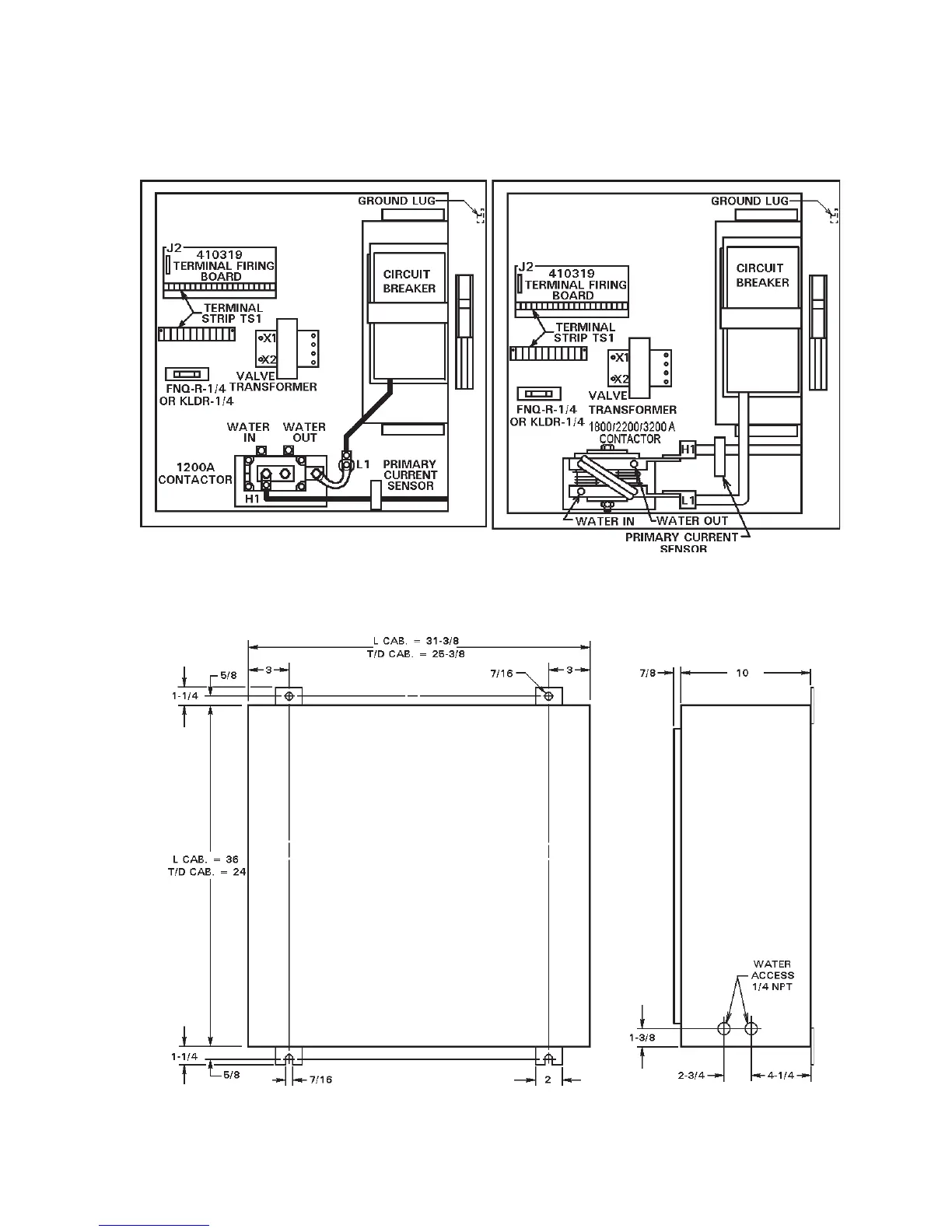
3.3 INSTALLATION AND MOUNTING DIAGRAMS – “T/D” AND “L”
CABINET
Style “T/D” and “L” Cabinet installation and mounting diagrams are shown in Figures 3-5, 3-6
and 3-7.
Figure 3-5. Installation of Style “T/D” and
“L” Cabinets – 1200A Contactor
Figure 3-6. Installation of Style “T/D” and
“L” Cabinets – 1800/2200/3200A Contactor
Figure 3-7. Mechanical mounting diagram for “T/D” and “L” Cabinets

 Loading...
