ENTRON Controls, LLC. • 700120S • Page 105
8.4.2 SETTING UP CURRENT REGULATOR – BOARDS WITH PROMS
BEFORE FIRMWARE VERSION 619016-001R
(for archival purpose only)
1. Setup must be done in SPOT mode (
S.E.S.E.
S.E.S.E.
S.E.=
0000
0000
00). If doing seam welding, re-program parameter
S.E.S.E.
S.E.S.E.
S.E. after setup. The control must be initiated using a FS3 initiation switch connected between
TS1-FS3 and TS1-GND. If the machine does not have initiations using this terminal,
temporarily connect a switch to FS3.
2. Using schedule 01, make sample welds in NON-CONSTANT CURRENT mode (
C.rC.r
C.rC.r
C.r
..
..
.=
0000
0000
00)
to determine the proper welding transformer tap switch setting. PERCENT CURRENT
should be between 70% and 80%* and WELD time should be the recommended number of
cycles for material being welded.
*
In order for the control to adapt to changing conditions, it must be able to adjust current. If weld is made
around 75%, the control can move up to 99% or down to 20% if necessary to maintain current constant
when the control is in CONSTANT CURRENT mode.
DO NOT USE SCHEDULE 00 IN STEP 2!
3. Switch to PROGRAM mode.
a) Select EXTENDED FUNCTION
C.rC.r
C.rC.r
C.r
..
..
., program
1010
1010
10, and press ENTER.
b) Select EXTENDED FUNCTION
rr
rr
r
.A..A.
.A..A.
.A., program
00.9900.99
00.9900.99
00.99, and press ENTER.
c) Select EXTENDED FUNCTION
C.A.C.A.
C.A.C.A.
C.A., program
0404
0404
04, and press ENTER. This presets
schedule 00 with specific setup parameters, including 30 cycles of SQUEEZE time and
VALVE 1 output.
d) You may change SQUEEZE time to match machine requirements, and press ENTER.
e) You may change VALVE Output to match machine requirements, and press ENTER.
DO NOT MAKE ANY OTHER CHANGES!
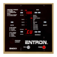
4. Switch to OPERATE mode. At this time, the DATA display
should flash
S.e.t.S.e.t.
S.e.t.S.e.t.
S.e.t.
5. Using the same material already welded **, insert it between
the machine electrodes, initiate a weld sequence and hold
the initiation switch closed. The machine electrodes will
close and the control will sequence through a preset test
schedule. When it is finished, it will display ERROR CODE
0505
0505
05.
** While in setup, the control makes multiple welds at 99% for 4
cycles. If the part being welded cannot support weld times of 4
cycles at 99% without expulsion or distortion, the parameters
measured may not provide correct setup data. In this case, run the
setup with no material between the electrodes.
6. Release the initiation switch. The control is now set up and
ready to operate. PERCENT CURRENT must be re-
programmed now as a four-digit number (example: 80% =
00800080
00800080
0080).
NOTICE
NOTICE

 Loading...