Page 158 • 700120S • ENTRON Controls, LLC.
APPENDIX F EN1003 THREE PHASE DC CONTROLS
Wiring Diagrams
EN1003 Controls in “L” & “H” Cabinets – 421291 Series
EN1003 Controls in “T/D” Cabinets – 421310 Series
Three Phase DC applications are frequently characterized by:
1. High weld current requirements typically with poor secondary power factor
configurations.
2. One common core transformer or three individual transformers connected three phase.
3. Secondary diode configurations of either half or full wave rectification.
Typical jobs that require DC weld controls are those that require either large secondary currents
or, by design, have high power losses caused by ferrous metals in the throat of the welder, such
as parts of the machine and/or welded parts. Because of the DC current, rather than AC, in the
secondary path, inductive losses are cut to a minimum and only resistive losses are of a concern.
This Appendix is to be used in conjunction with Wiring Diagram 421291 (“L” & “H” Cabinets)
or 421310 (“T/D” Cabinets) and this manual, which is applicable to all models in the EN1003
Series. However, some sections of this manual apply only to EN1000 and EN1001 Series Single
Phase Controls and should be disregarded for EN1003 Controls.
Sections to be disregared are as follows:
Section 1.1 (Standard Features) – Notice concerning 60 Hz or 50 Hz operation
Sections 3.1, 3.2, 3.3, 3.4, 3.5 (Installation and Mounting Diagrams)
Section 3.6 (Welding Tranformer Primary Wiring)
Section 3.7 (External SCR Contactor Wiring)
Section 4.1 (Operating Voltage)
Section 4.2 (Fusing)
Section 4.3.3 (Terminal Strip TS1 Inside the Cabinet)
Information contained in this Appendix and on Wiring Diagrams replaces the information
contained in these sections.
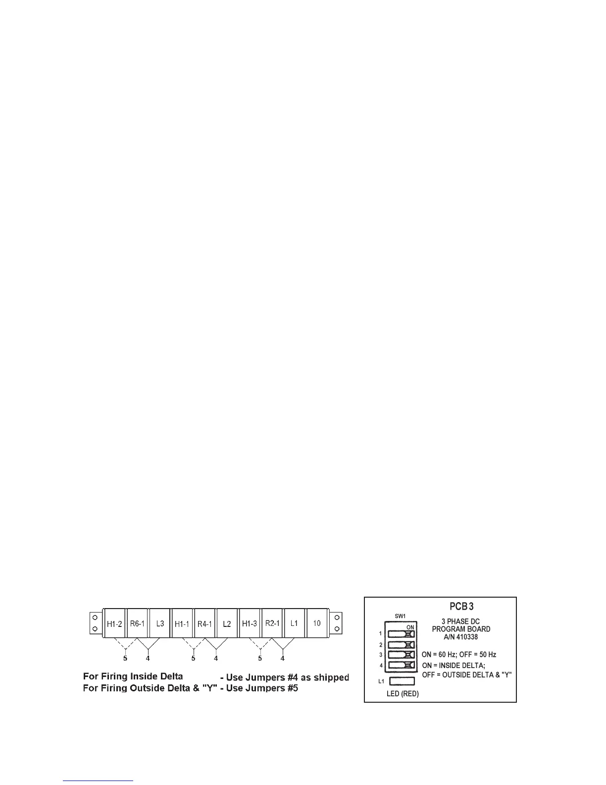
All EN1003 models fire three welding contactors, controlled by one digital phase shift heat
control setting, and may be connected to the welding transformers in an outside delta, inside
delta, or “Y” configuration (see Figures F-6 and F-7). Jumpers on TS10 Terminal Strip (Figure
F-1) and SW1 position #4 (Figure F-2) on PCB3 (A/N 410338) must be set accordingly; also
see Views “B”, “C”, “D” and Note 2 on Wiring Diagrams. Transformer secondaries may be
connected for half wave or full wave rectification.
Figure F-1. TS10 connections Figure F-2. PCB3 SW1 and L1

 Loading...
