ENTRON Controls, LLC. • 700120S • Page 11
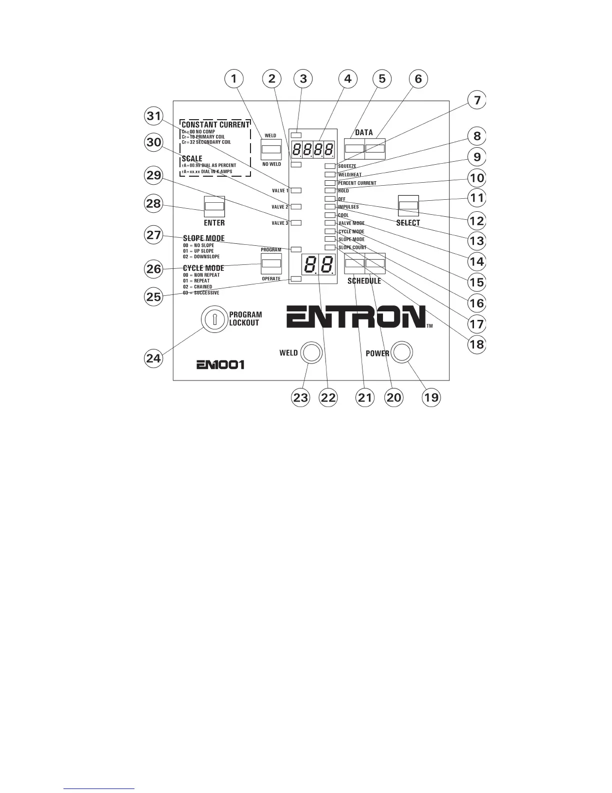
1.2 CONTROL PANEL LAYOUT
1 - WELD/NO WELD push button 17 - SLOPE MODE function indicator LED*
2 - NO WELD mode indicator LED 18 - SLOPE COUNT function indicator LED
3 - WELD mode indicator LED 19 - POWER light (red)
4 - DATA display 20 - SCHEDULE 1s push button
5 - DATA 10s push button 21 - SCHEDULE 10s push button
6 - DATA 1s push button 22 - SCHEDULE display
7 - SQUEEZE function indicator LED 23 - WELD light (white)
8 - WELD/HEAT function indicator LED 24 - PROGRAM LOCKOUT key switch
9 - PERCENT CURRENT function indicator LED 25 - OPERATE mode indicator LED
10 - HOLD function indicator LED 26 - PROGRAM/OPERATE push button
11 - SELECT push button 27 - PROGRAM mode indicator LED
12 - OFF function indicator LED 28 - ENTER push button
13 - IMPULSES function indicator LED 29 - VALVE 3 indicator LED
14 - COOL function indicator LED 30 - VALVE 2 indicator LED
15 - VALVE MODE function indicator LED 31 - VALVE 1 indicator LED
16 - CYCLE MODE function indicator LED*
* For operator convenience, codes for SLOPE MODE and CYCLE MODE functions are printed
on the left side of the Control Panel.
On EN1000 Control Panel layout, there is no added text for CONSTANT CURRENT modes.
Figure 1-2. Control Panel layout

 Loading...
