Page 162 • 700120S • ENTRON Controls, LLC.
APPENDIX H IMU MOUNTING OPTIONS
The Integrated Modular Unit (IMU) series of Weld Controls are designed for use in retrofit
situations or in new/custom designs. Customers are free to place one or more of these units in
existing enclosures or new designs as requirements demand. To make the IMU even more
flexible, the rear chassis can be rotated 180
EE
EE
E. If the IMU as supplied cannot be oriented so
that the Terminal Strip/Firing PCB, Voltage Programming Terminal Strip and fuse holder can
be accessed directly, the chassis can be inverted (turned upside down) to provide access as
shown in Figure H-1. Before installing the IMU in an enclosure, determine whether or not the
chassis needs to be flipped. If rotation of the chassis is required, follow the instructions below.
1. Unplug the J2, J3, Weld light and Power light terminal connections, mark the wires for
reconnection later.
2. Remove and retain the four 6-32 nuts and split lock washers that attach the IMU mounting
brackets to the Dial Plate.
3. Rotate the IMU chassis 180E on its long axis and remount the brackets to the studs on the
Dial Plate (see Figure H-1).
4. Extend the J2 and Power light harnesses from their tied-back positions and reconnect all
the connections removed above.
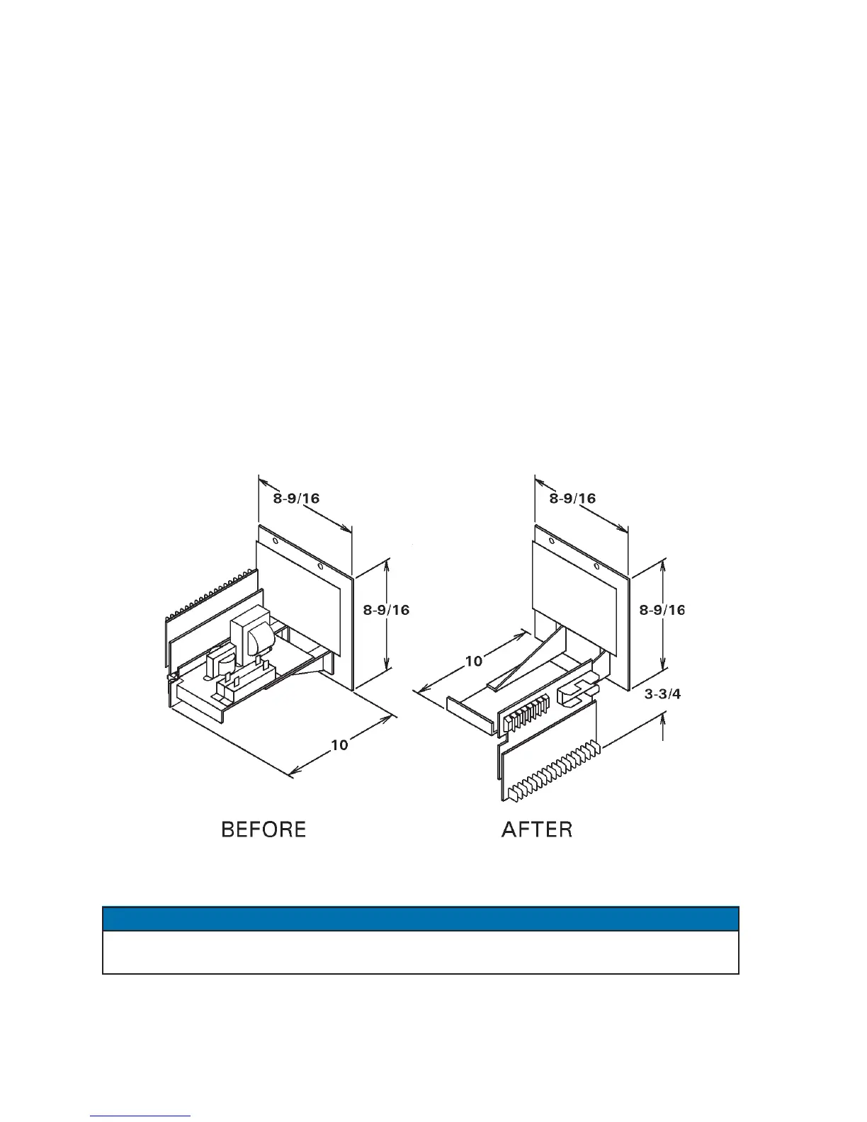
Figure H-1. IMU rotation option
The standard IMU configuration on the left does not require as much clearance space below
the Dial Plate mounting as the new configuration on the right.
NOTICE

 Loading...
