Page 98 • 700120S • ENTRON Controls, LLC.
To obtain the proper signal, the sensor selection jumper must be set on the correct position
dependent on type of Current Sensor used:
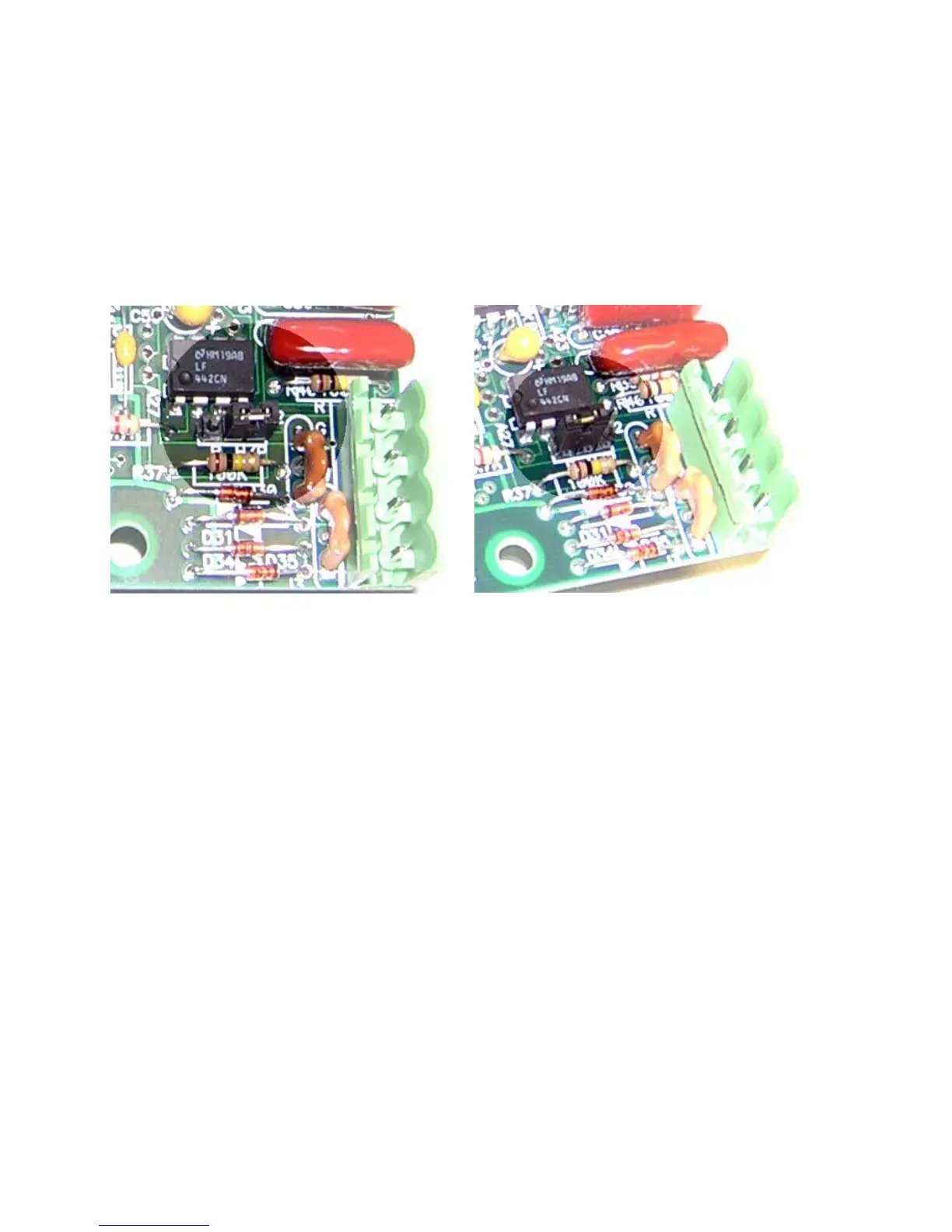
1. If the control is connected with a Primary Current Transformer, the sensor selection
jumper should be put on the two pins on the right, as shown in Figure 8-1.
2. If the control is connected with a Secondary Rogowski Coil, the sensor selection jumper
should be put on the two pins on the left, as shown in Figure 8-2.
This hardware setup must be done when the control is initially installed, when a new different
type of Current Sensor is connected with the control or control board is exchanged.
8.2 SOFTWARE PARAMETERS SETUP
The following working modes have been defined for the EN1001 Control:
1. SECONDARY PRESET-RANGE COMPENSATION or MONITORING mode with
Rogowski Coil –
C.rC.r
C.rC.r
C.r
..
..
.=
3232
3232
32 or
3333
3333
33
2. PRIMARY PRESET-RANGE COMPENSATION or MONITORING mode with Current
Transformer –
C.rC.r
C.rC.r
C.r
..
..
.=
1212
1212
12 through
1919
1919
19
3. SECONDARY AUTO-RANGE COMPENSATION or MONITORING mode with
Rogowski Coil –
C.rC.r
C.rC.r
C.r
..
..
.=
3030
3030
30 or
3131
3131
31
4. PRIMARY AUTO-RANGE COMPENSATION or MONITORING mode with Current
Transformer –
C.rC.r
C.rC.r
C.r
..
..
.=
1010
1010
10 or
11
11
1
11
11
1
These working modes are used to inform the control which Current Sensor has been connected
and which current setting will be used to input data. The control will then automatically adjust
the gain of the embedded amplifier and control the working current at the desired value.
Before CONSTANT CURRENT function is operational, the operator must inform the control
which working mode is selected by setting the proper EXTENDED FUNCTION parameters
t.rt.r
t.rt.r
t.r
..
..
.,
C.rC.r
C.rC.r
C.r
..
..
., and
rr
rr
r
.A..A.
.A..A.
.A. The instructions for programming
t.rt.r
t.rt.r
t.r
..
..
.,
C.rC.r
C.rC.r
C.r
..
..
., and
rr
rr
r
.A..A.
.A..A.
.A. are described in Sections
5.4.14, 5.4.15 and 5.4.16.
8.1 HARDWARE SETUP (cont.)
Figure 8-1. Jumper setting:
Primary Current Transformer
(two pins on the right)
Figure 8-2. Jumper setting:
Secondary Rogowski Coil
(two pins on the left)

 Loading...
