ENTRON Controls, LLC. • 700120S • Page 123
9.7 PROCESS OUTPUT
2626
2626
26
HOLD PART IN WELDER IF CURRENT OUT OF LIMIT WINDOW
This PROCESS OUTPUT requires the use of EN1001 Control Board Assembly No. 600572
with PROM firmware version 619016-002C or later. See Section 4.7 for information about
Isolation Contactors and Section 8.3.2 for programming HIGH and LOW CURRENT limits.
When
PP
PP
P
.O..O.
.O..O.
.O.=
2626
2626
26, the weld control (when wired to the machine as shown in Figure 9-17) will hold
the part just previously welded, between the electrodes, if the measured current is not between
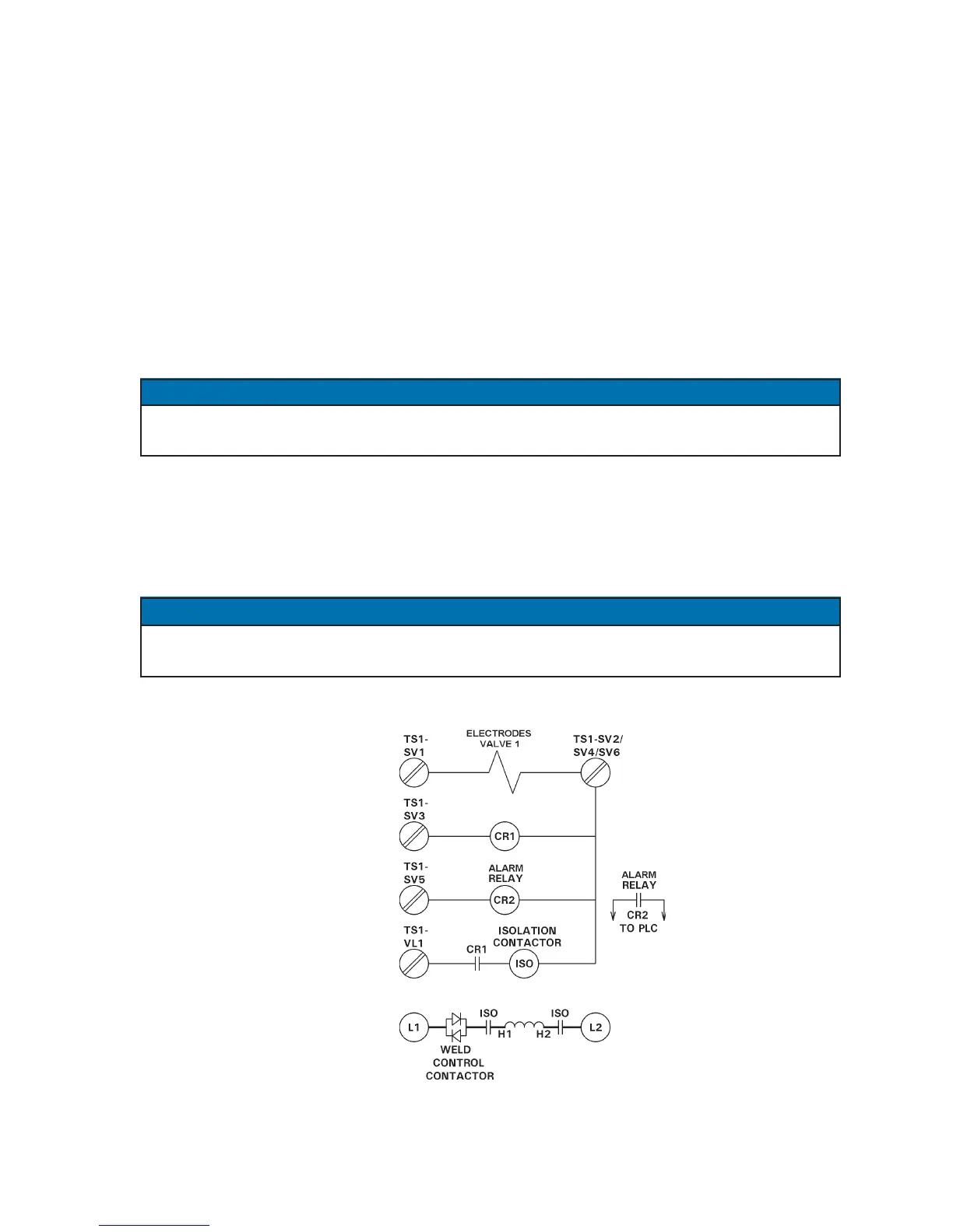
the programmed HIGH/LOW limit window. The valve assignment must be as follows:
Valve 1 TS1-SV1 Connects to Valve 1 for Electrodes
Valve 2 TS1-SV3 Connects to CR1 which drives Magnetic Isolation Contactor
Valve 3 TS1-SV5 Connects to Alarm Output CR2
On weld controls with a PROGRAM LOCKOUT key switch, the key must be rotated and
error cleared before the part can be removed from the welder.
9.7.1 VALVE 1 (Welding Head Solenoid Output for Electrodes)
Program desired schedule using Valve 1 for SQUEEZE, WELD, and HOLD times (set VALVE
MODE=
0303
0303
03).
This valve will stay on after the sequence is complete if current is out of programmed HIGH/
LO limit window. If current is within limit window, the valve will turn off at end of HOLD.
Figure 9-17. PROCESS OUTPUT
2626
2626
26 wiring
NOTICE
NOTICE
VALVE 1
VALVE 2
VALVE 3

 Loading...
