ENTRON Controls, LLC. • 700120S • Page 99
8.2.1 SECONDARY PRESET-RANGE COMPENSATION OR MONITORING
MODE WITH ROGOWSKI COIL
In these modes, a learning-type setup process is not required. However,
rr
rr
r
.A..A.
.A..A.
.A. must be programmed
for the desired CURRENT range in which the machine will operate. Available values of
rr
rr
r
.A..A.
.A..A.
.A. are
shown in Table 8-1. If the desired range of
rr
rr
r
.A..A.
.A..A.
.A. is far below or far above operating range,
current overshooting or poor compensation will result.
COMPENSATION
With
C.rC.r
C.rC.r
C.r
..
..
.=
3232
3232
32, the control will operate in SECONDARY PRESET-RANGE COMPENSATION
mode with Rogowski Coil. When the control operates in this COMPENSATION mode, the
value of PERCENT CURRENT setting in the weld schedules should be input as the required
secondary output current in [kA].
MONITORING
With
C.rC.r
C.rC.r
C.r
..
..
.=
3333
3333
33, the control will operate in SECONDARY PRESET-RANGE MONITORING mode
with Rogowski Coil. When the control operates in this MONITORING mode, the control will
only display the weld current after a weld but will not compensate the current error. The value
of PERCENT CURRENT setting in the weld schedules should be input as the percentage [%]
of maximum current output of the control.
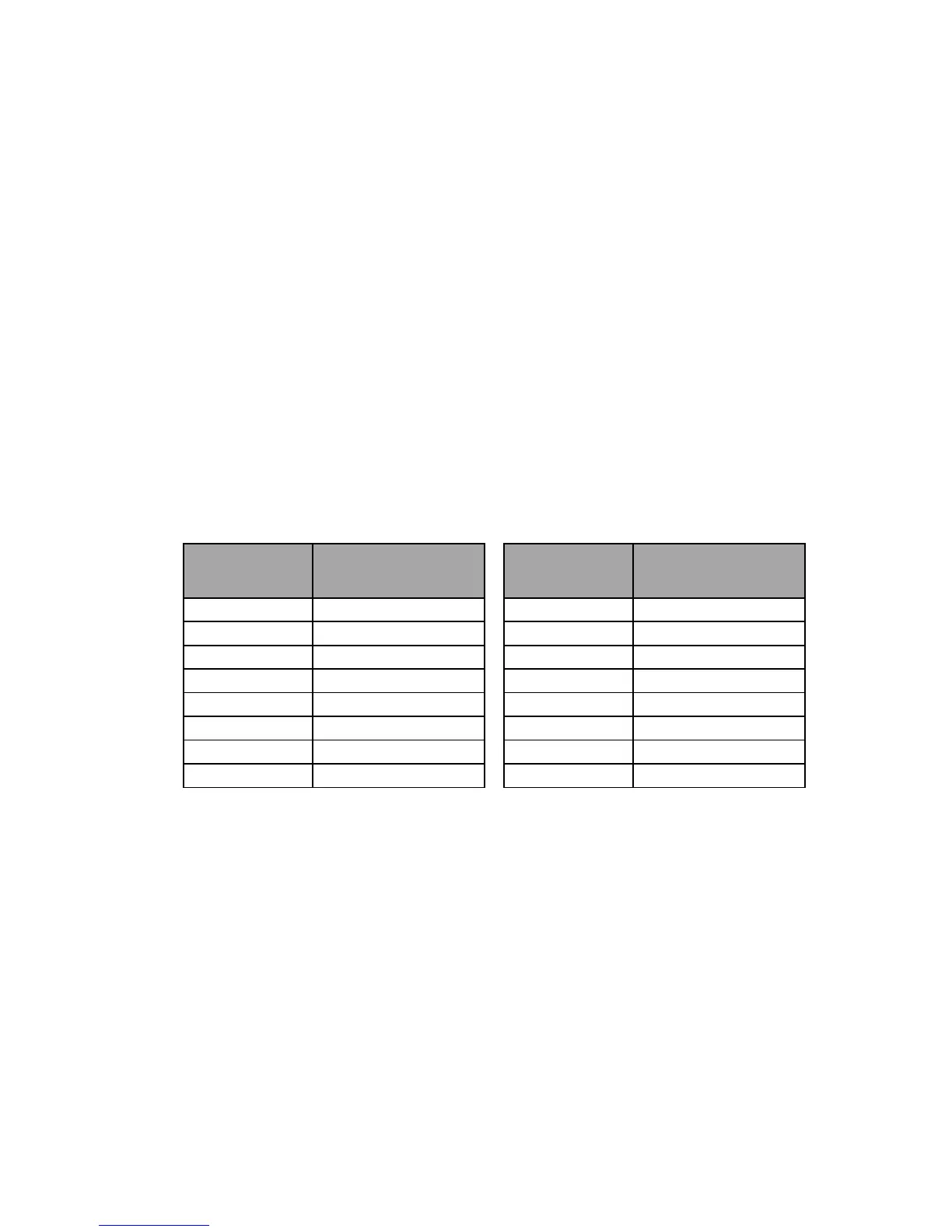
Table 8-1. Operating Ranges for Preset-Range Selection with Rogowski Coil
8.2.2 PRIMARY PRESET-RANGE COMPENSATION OR MONITORING
MODE WITH CURRENT TRANSFORMER
In these modes, a learning-type setup process is not required.
rr
rr
r
.A..A.
.A..A.
.A. should be set to the desired
secondary CURRENT range, and
t.rt.r
t.rt.r
t.r
..
..
. should be set to the TURNS RATIO of the transformer.
The maximum values of
rr
rr
r
.A..A.
.A..A.
.A. are limited by the maximum value of current transformer and the
turns ratio of transformer, the relation is shown by the following equation:
Maximum
rr
rr
r
.A..A.
.A..A.
.A. = Maximum Current of current sensor x Turns Ratio of transformer
COMPENSATION
With
C.rC.r
C.rC.r
C.r
..
..
.=
1212
1212
12,
1414
1414
14,
1616
1616
16 or
1818
1818
18 if using PT2, PT5, PT10 or PT20 as Current Sensor, the control will
operate in PRIMARY PRESET-RANGE COMPENSATION mode. When the control operates
in this COMPENSATION mode, the value of CURRENT setting in the weld schedules should
be input as the desired secondary current in [kA] value.
Current Range
in kA
RANGE Parameter
Current Range
in kA
RANGE Parameter
0 to 2 02.00 0 to 30 30.00
0 to 3 03.00 0 to 40 40.00
0 to 4 04.00 0 to 50 50.00
0 to 5 05.00 0 to 60 60.00
0 to 6 06.00 0 to 70 70.00
0 to 8 08.00 0 to 80 80.00
0 to 10 10.00 0 to 90 90.00
0 to 20 20.00 0 to 100 99.99

 Loading...
