Page 14 • 700120S • ENTRON Controls, LLC.
To put the control back in the OPERATE mode:
Press the PROGRAM/OPERATE push button again. The control will return to the
OPERATE mode without the necessity of rotating the key.
See Section 5.4.18 for detailed information on PIN LOCKOUT mode.
ENTER PUSH BUTTON (28) – The ENTER push button is used to store the data shown
from the DATA display into the non-volatile memory which retains data with the power off.
If ENTER is not pressed before other data is viewed (by pressing the SELECT push button)
or before returning to the OPERATE mode, the data will not be stored; however, it is not
necessary to press the ENTER push button to save the four-digit DATA display.
VALVE INDICATOR LEDs (29, 30, & 31) – These three LEDs indicate, in the OPERATE
mode, when the solenoid valves are activated in the control program. In the PROGRAM mode,
these same LEDs indicate the valve chosen for the weld sequence (schedule) being programmed.
Codes for valve selection are given in Table 2-3.
2.2 SEQUENCE TIMED PARAMETERS (Count Functions)
SQUEEZE .................................................... Programmable from 0 to 99 cycles (50/60 Hz)
WELD/HEAT ................................................ Programmable from 0 to 99 cycles (50/60 Hz)
HOLD ........................................................... Programmable from 0 to 99 cycles (50/60 Hz)
OFF .............................................................. Programmable from 0 to 99 cycles (50/60 Hz)
IMPULSES ................................................... Programmable from 1 to 99
COOL ........................................................... Programmable from 0 to 99 cycles (50/60 Hz)
SLOPE COUNT ........................................... Programmable from 0 to 99 cycles (50/60 Hz)
NO ADJUSTMENT is required for timing to change from 60 to 50 Hz operation.
SQUEEZE COUNT (7) – The time duration for the electrodes to close on the work and
build up pressure before WELD time begins.
WELD/HEAT COUNT (8) – The time during which current will flow through the welding
transformer (during one impulse in impulse welding). It starts after SQUEEZE or after the
closure of a Pressure Switch, whichever occurs last.
HOLD COUNT (10) – The time during which the electrodes will remain in contact with
the work to allow the weld nugget to congeal. It starts after the WELD time.
OFF COUNT (12) – In the REPEAT mode, the time duration between HOLD count and
SQUEEZE count to allow the work to be repositioned.
COOL COUNT (14) – The time between heat IMPULSES (in multiple impulse welding).
SLOPE COUNT (18) – The number of additional WELD cycles during which PERCENT
CURRENT increases or decreases to achieve SLOPE (gradual increase or decrease in current).
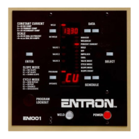
2.1 CONTROL FUNCTIONS (cont.) – See Figure 1-2. Control Panel layout
NOTICE
NOTICE

 Loading...