Page 82 • 700120S • ENTRON Controls, LLC.
When the EXTENDED FUNCTION SCHEDULE SELECT is programmed to the EXTERNAL
mode, the SUCCESSIVE series will start with the externally selected schedule and will
automatically return to that schedule once the series is completed (see Section 5.4.3).
The BACK-STEP function can be used to return to the previous schedule N-1 without continuing
through the rest of the SUCCESSIVE schedules. A momentary closure of the BACK-STEP
(TLS1/AUX1) switch will cause the control to return the previous schedule. This can be repeated
until the first schedule of a series is reached. A maintained closure (approximately 1.5 seconds)
will cause the control to return the first schedule in the series. If the BACK-STEP switch is
maintained after the control reaches the first schedule, an ERROR CODE
E.rE.r
E.rE.r
E.r
..
..
.=
0606
0606
06 will flash in
the DATA display. See Section 5.4.6.
6.2.5 CONDITIONAL SUCCESSIVE – CYCLE MODE=
0404
0404
04
The CONDITIONAL SUCCESSIVE mode has been implemented to complement CHAINED
and SUCCESSIVE sequences with a third type that combines the benefits of both.
The control will execute the given schedule, and at the end of HOLD will maintain the schedule
valves active. At this point, the control will wait in this state and indicate the state by blinking
the Front Panel HOLD LED. If the control is initiated a second time, when the initiation input
closes, the control will continue by selecting the next schedule and executing it as programmed.
EXAMPLE: PART LOCATOR & CLAMP
In some cases fixturing may require a locating pin be extended to accurately locate a part before
welding. The following shows how three schedules can be programmed using various CYCLE
MODES to accomplish this function.
Step 1 – Locate
Schedule 00 is programmed to energize Valve 1 in order to actuate a part locator. Initially, the
valve is active for 60 cycles, 40 cycles of SQUEEZE and 20 cycles of HOLD (one second). At
the end of this time, the control blinks the HOLD LED and waits for further input; i.e., for re-
initiation.
At this point, the operator can load a part and initiate the next sequence by opening and closing
the foot switch.
Step 2 – Clamp
When the operator closes the foot switch again, the control activates the following CHAINED
schedule immediately. During the second schedule, the control adds a second valve to the first,
the clamp valve.
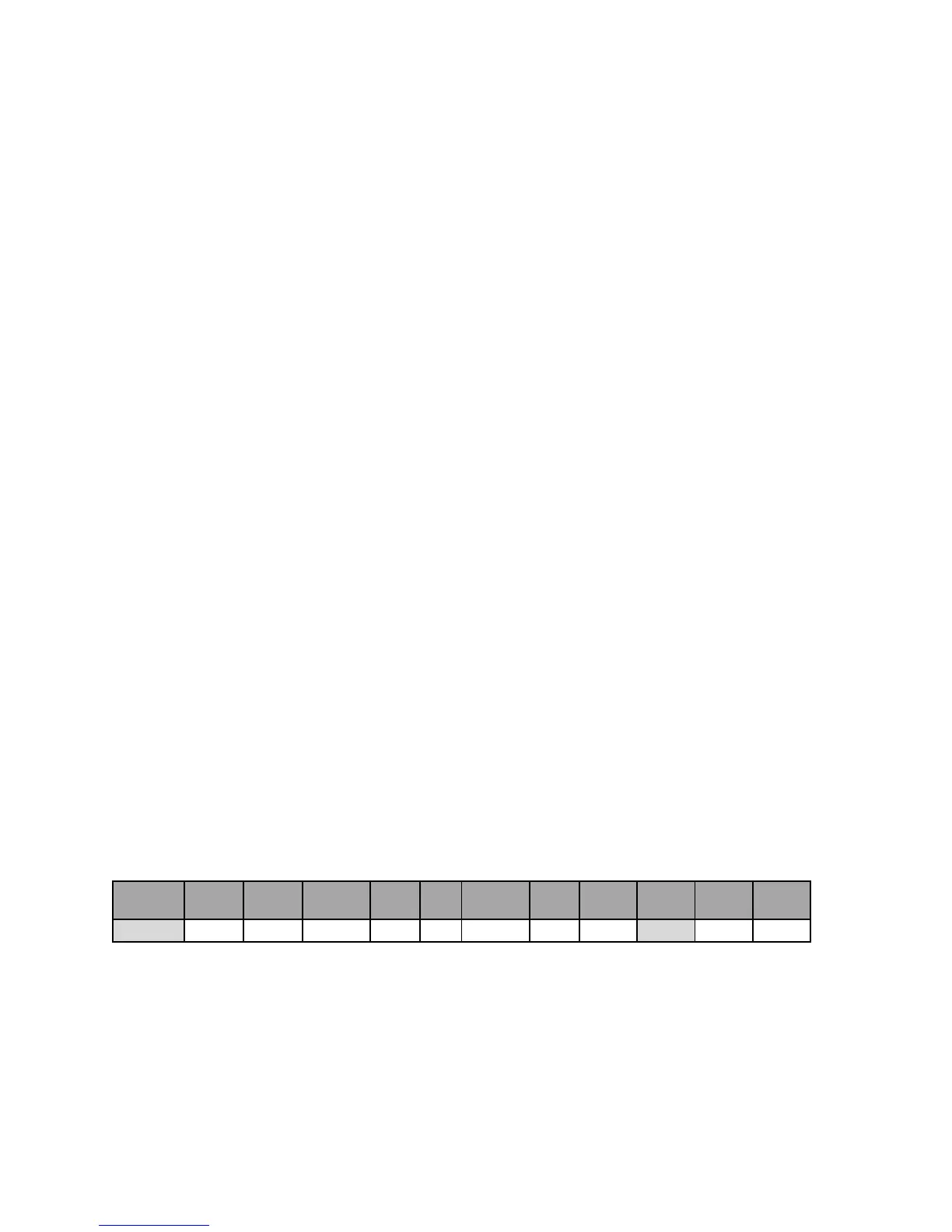
6.2.4 SUCCESSIVE – CYCLE MODE=
0303
0303
03 (cont.)
SCHEDULE SQUEEZE
WELD/
HEAT
PERCENT
CURRENT
HOLD OFF IMPULSES COOL
VALVE
MODE
CYCLE
MODE
SLOPE
MODE
SLOPE
COUNT
00 40 00 00 20 00 01 00 01 04 00 00

 Loading...
